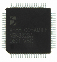
XE8805AMI028LF Semtech, XE8805AMI028LF Datasheet - Page 85

XE8805AMI028LF
Manufacturer Part Number
XE8805AMI028LF
Description
IC DAS 16BIT FLASH 8K MTP 64LQFP
Manufacturer
Semtech
Datasheet
1.XE8805AMI028LF.pdf
(156 pages)
Specifications of XE8805AMI028LF
Applications
Sensing Machine
Core Processor
RISC
Program Memory Type
FLASH (22 kB)
Controller Series
XE8000
Ram Size
512 x 8
Interface
UART, USRT
Number Of I /o
24
Voltage - Supply
2.4 V ~ 5.5 V
Operating Temperature
-40°C ~ 85°C
Mounting Type
Surface Mount
Package / Case
64-LQFP
Supply Voltage Range
2.4V To 5.5V
Operating Temperature Range
-40°C To +85°C
Digital Ic Case Style
LQFP
No. Of Pins
64
For Use With
XE8000MP - PROG BOARD AND PROSTART2 CARD
Lead Free Status / RoHS Status
Lead free / RoHS Compliant
Available stocks
Company
Part Number
Manufacturer
Quantity
Price
Part Number:
XE8805AMI028LF
Manufacturer:
SEMTECH/美国升特
Quantity:
20 000
Condition 2 is satisfied when S0=1 at the rising edge of S1. The bit UsrtCond2 in RegUsrtCond2 is set when the
condition 2 is detected and the USRT interface is enabled. Condition 2 is asserted for both modes (receiver and
transmitter). The UsrtCond2 bit is read only and is cleared by all reset conditions and by writing any data to its
address.
Condition 2 occurrence also generates an interrupt on Irq_cond2.
15.7 Interrupts or polling
In receive mode, there are two possibilities for detecting condition 1 or 2: the detection of the condition can
generate an interrupt or the registers can be polled (reading and checking the RegUsrtCond1 and RegUsrtCond2
registers for the status of USRT communication).
15.8 Function description
The bit UsrtEnable in RegUsrtCtrl is used to enable the USRT interface and controls the PB[4] and PB[5] pins.
This bit puts these two port B lines in the open drain configuration requested to use the USRT interface.
If no external pull-ups are added on PB[4] and PB[5], the user can activate internal pull-ups by setting PBPullup[4]
and PBPullup[5] in RegPBPullup.
The bits UsrtEnWaitS0, UsrtEnWaitCond1, UsrtWaitS0 in RegUsrtCtrl are used for transmitter/receiver control
of USRT interface.
Figure 15-3 shows the unconditional clock stretching function which is enabled by setting UsrtEnWaitS0.
When UsrtEnWaitS0 is 1, the S0 line will be maintained at 0 after its falling edge (clock stretching). UsrtWaitS0 is
then set to 1, indicating that the S0 line is forced low. One can release S0 by writing to the RegUsrtBufferS1
register.
The same can be done in combination with condition 1 detection by setting the UsrtEnWaitCond1 bit. Figure 15-4
shows the conditional clock stretching function which is enabled by setting UsrtEnWaitCond1.
© Semtech 2006
S0
UsrtWaitS0
write Reg UsrtBufferS1
Figure 15-3: S0 Stretching (UsrtEnWaitS0=1)
15-5
XE8805/05A
www.semtech.com


