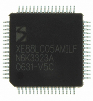
XE8805AMI028LF Semtech, XE8805AMI028LF Datasheet - Page 125

XE8805AMI028LF
Manufacturer Part Number
XE8805AMI028LF
Description
IC DAS 16BIT FLASH 8K MTP 64LQFP
Manufacturer
Semtech
Datasheet
1.XE8805AMI028LF.pdf
(156 pages)
Specifications of XE8805AMI028LF
Applications
Sensing Machine
Core Processor
RISC
Program Memory Type
FLASH (22 kB)
Controller Series
XE8000
Ram Size
512 x 8
Interface
UART, USRT
Number Of I /o
24
Voltage - Supply
2.4 V ~ 5.5 V
Operating Temperature
-40°C ~ 85°C
Mounting Type
Surface Mount
Package / Case
64-LQFP
Supply Voltage Range
2.4V To 5.5V
Operating Temperature Range
-40°C To +85°C
Digital Ic Case Style
LQFP
No. Of Pins
64
For Use With
XE8000MP - PROG BOARD AND PROSTART2 CARD
Lead Free Status / RoHS Status
Lead free / RoHS Compliant
Available stocks
Company
Part Number
Manufacturer
Quantity
Price
Part Number:
XE8805AMI028LF
Manufacturer:
SEMTECH/美国升特
Quantity:
20 000
18.4 The D/A description
The D/A converter consists of 2 parts: a classic PWM modulator which is preceded by a noise shaper (Figure
18-1). The PWM signal has then to be low pass filtered using the amplifier and external components to obtain the
analog signal.
18.4.1
The major disadvantage of using a PWM modulator to generate a high resolution analog signal is that it requires a
high ratio between the PWM switching frequency and the useful bandwidth of the output analog signal after low
pass filtering.
Example: assuming the switching frequency of the PWM modulator is 1MHz and one wants to resolve 16 bit, i.e.
2
65536µs per pulse. This means that the PWM pulse repetition rate is 1/65536µs=15.25Hz. So, even with a higher
order low pass filter, more than 1 frequency decade will be required to filter the PWM signal down to a 16 bit
accurate analog signal. This leaves a useful bandwidth below 1Hz.
The goal of the noise shaper is to reduce the ratio between the PWM switching frequency and the useful
bandwidth. The noise shaper will not reduce the “truncation noise” and “PWM modulation noise” but move it to
higher frequencies. It “shapes” the frequency spectrum (“noise”) of the generated PWM signal, hence its name. In
practice, the noise shaper allows the generation of a signal with a given resolution using a PWM modulator that
has a lower resolution. The noise shaper then generates a series of different subsequent low resolution codes for
the PWM so that the average value corresponds to the high resolution code.
The first order noise shaper interpolates between two adjacent PWM codes to obtain a higher resolution. The
second order noise shaper can use non-adjacent PWM codes.
Example for first order noise shaper: assuming again the resolution of 16 bits using a 1MHz PWM switching
frequency using the noise shaper with order 1. If a PWM modulator with 4 bits, i.e. 16 steps is used, the PWM
repetition frequency becomes then 1MHz/16=62.5kHz. The PWM modulator can convert only the 4 MSB’s of the
16 bit input such as h0000, h1000 until hF000. In order to convert the code h5800, which is between h5000 and
h6000? In this case, the first order noise shaper will interpolate by presenting alternatively the code h5 and h6 to
the PWM so that after filtering a signal is obtained halfway between the normal PWM steps. To convert the code
h5400, it will present h5 3 times and h6 once to the PWM and so on. It is clear from this that the PWM repetition
frequency is much higher than for the simple PWM and can be filtered out more easily. The quantization noise
frequency will depend on the code to be converted: for this example for instance we need two PWM pulses to
implement the code h5800, but we need four to implement h5400 etc.
Example for second order noise shaper: if we use the same conditions as for the example above, we will obtain the
same PWM repetition frequency. However, to implement the code h5400, the noise shaper now can present the
following sequence to the PWM modulator: h6, h5, h6, h4. This increases the frequency components at the PWM
pulse repetition frequency and ½ of the PWM pulse repetition frequency but at the same time reduces energy at ¼
of the PWM pulse repetition frequency with respect to the first order noise shaper. The low pass cut-off frequency
can therefore be higher than for a first order noise shaper.
A disadvantage of the second order noise shaper is however that the resolution will drop when the code is very
close to h0000 or hFFFF.
Example: if we assume the same conditions as above, but we want to convert the code h0400. It is now impossible
to use a similar sequence as above (which would be h1, h0, h1, h(-1) ) due to saturation of the code. There is no
choice left but the sequence h1 h0 h0 h0 which is the same sequence as in the first order noise shaper.
18.4.2
Advantages:
Using a high order noise shaper together with a PWM modulator with low resolution reduces the ratio between the
low pass cut off frequency and the PWM switching frequency for the same total resolution. This can be used to
© Semtech 2006
16
=65536 steps. In this case, the PWM has to code each step in increments of 1µs=1/1MHz and needs therefore
What is a noise shaper?
Advantages/disadvantages
18-4
XE8805/05A
www.semtech.com


