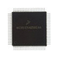
MC9S12C128VFU Freescale Semiconductor, MC9S12C128VFU Datasheet - Page 626

MC9S12C128VFU
Manufacturer Part Number
MC9S12C128VFU
Description
Manufacturer
Freescale Semiconductor
Datasheet
1.MC9S12C128VFU.pdf
(690 pages)
Specifications of MC9S12C128VFU
Cpu Family
HCS12
Device Core Size
16b
Frequency (max)
25MHz
Interface Type
CAN/SCI/SPI
Program Memory Type
Flash
Program Memory Size
128KB
Total Internal Ram Size
4KB
# I/os (max)
60
Number Of Timers - General Purpose
8
Operating Supply Voltage (typ)
2.5/5V
Operating Supply Voltage (max)
2.75/5.5V
Operating Supply Voltage (min)
2.35/2.97V
On-chip Adc
8-chx10-bit
Instruction Set Architecture
CISC
Operating Temp Range
-40C to 105C
Operating Temperature Classification
Industrial
Mounting
Surface Mount
Pin Count
80
Package Type
PQFP
Lead Free Status / Rohs Status
Not Compliant
Available stocks
Company
Part Number
Manufacturer
Quantity
Price
Company:
Part Number:
MC9S12C128VFUE
Manufacturer:
Freescale
Quantity:
38 000
Company:
Part Number:
MC9S12C128VFUE
Manufacturer:
Freescale Semiconductor
Quantity:
10 000
- Current page: 626 of 690
- Download datasheet (4Mb)
Chapter 21 128 Kbyte Flash Module (S12FTS128K1V1)
21.3.2.7
The FCMD register defines the Flash commands.
Bits CMDB6, CMDB5, CMDB2, and CMDB0 are readable and writable during a command write
sequence while bits 7, 4, 3, and 1 read 0 and are not writable.
626
Module Base + 0x0006
ACCERR
BLANK
Reset
PVIOL
DONE
Field
FAIL
5
4
2
1
0
W
R
Protection Violation — The PVIOL flag indicates an attempt was made to program or erase an address in a
protected Flash array memory area. The PVIOL flag is cleared by writing a 1 to PVIOL. Writing a 0 to the PVIOL
flag has no effect on PVIOL. While PVIOL is set, it is not possible to launch another command.
0 No protection violation detected
1 Protection violation has occurred
Access Error — The ACCERR flag indicates an illegal access to the Flash array caused by either a violation of
the command write sequence, issuing an illegal command (illegal combination of the CMDBx bits in the FCMD
register) or the execution of a CPU STOP instruction while a command is executing (CCIF=0). The ACCERR flag
is cleared by writing a 1 to ACCERR. Writing a 0 to the ACCERR flag has no effect on ACCERR. While ACCERR
is set, it is not possible to launch another command.
0 No access error detected
1 Access error has occurred
Flash Array Has Been Verified as Erased — The BLANK flag indicates that an erase verify command has
checked the Flash array and found it to be erased. The BLANK flag is cleared by hardware when CBEIF is
cleared as part of a new valid command write sequence. Writing to the BLANK flag has no effect on BLANK.
0 If an erase verify command has been requested, and the CCIF flag is set, then a 0 in BLANK indicates the
1 Flash array verifies as erased
Flag Indicating a Failed Flash Operation — In special modes, the FAIL flag will set if the erase verify operation
fails (Flash array verified as not erased). Writing a 0 to the FAIL flag has no effect on FAIL. The FAIL flag is cleared
by writing a 1 to FAIL. While FAIL is set, it is not possible to launch another command.
0 Flash operation completed without error
1 Flash operation failed
Flag Indicating a Failed Operation is not Active — In special modes, the DONE flag will clear if a program,
erase, or erase verify operation is active.
0 Flash operation is active
1 Flash operation is not active
Flash Command Register (FCMD)
0
0
7
array is not erased
= Unimplemented or Reserved
CMDB6
0
6
Figure 21-11. Flash Command Register (FCMD)
Table 21-13. FSTAT Field Descriptions
CMDB5
MC9S12C-Family / MC9S12GC-Family
0
5
Rev 01.24
0
0
4
Description
0
0
3
CMDB2
0
2
Freescale Semiconductor
0
0
1
CMDB0
0
0
Related parts for MC9S12C128VFU
Image
Part Number
Description
Manufacturer
Datasheet
Request
R
Part Number:
Description:
Manufacturer:
Freescale Semiconductor, Inc
Datasheet:
Part Number:
Description:
Manufacturer:
Freescale Semiconductor, Inc
Datasheet:
Part Number:
Description:
Manufacturer:
Freescale Semiconductor, Inc
Datasheet:
Part Number:
Description:
Manufacturer:
Freescale Semiconductor, Inc
Datasheet:
Part Number:
Description:
Manufacturer:
Freescale Semiconductor, Inc
Datasheet:
Part Number:
Description:
Manufacturer:
Freescale Semiconductor, Inc
Datasheet:
Part Number:
Description:
Manufacturer:
Freescale Semiconductor, Inc
Datasheet:
Part Number:
Description:
Manufacturer:
Freescale Semiconductor, Inc
Datasheet:
Part Number:
Description:
Manufacturer:
Freescale Semiconductor, Inc
Datasheet:
Part Number:
Description:
Manufacturer:
Freescale Semiconductor, Inc
Datasheet:
Part Number:
Description:
Manufacturer:
Freescale Semiconductor, Inc
Datasheet:
Part Number:
Description:
Manufacturer:
Freescale Semiconductor, Inc
Datasheet:
Part Number:
Description:
Manufacturer:
Freescale Semiconductor, Inc
Datasheet:
Part Number:
Description:
Manufacturer:
Freescale Semiconductor, Inc
Datasheet:
Part Number:
Description:
Manufacturer:
Freescale Semiconductor, Inc
Datasheet:


