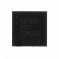
C8051T611-GM Silicon Laboratories Inc, C8051T611-GM Datasheet - Page 8

C8051T611-GM
Manufacturer Part Number
C8051T611-GM
Description
IC 8051 MCU 16K BYTE-PROG 28-QFN
Manufacturer
Silicon Laboratories Inc
Series
C8051T61xr
Specifications of C8051T611-GM
Core Processor
8051
Core Size
8-Bit
Speed
25MHz
Connectivity
SMBus (2-Wire/I²C), SPI, UART/USART
Peripherals
POR, PWM, Temp Sensor, WDT
Number Of I /o
25
Program Memory Size
16KB (16K x 8)
Program Memory Type
OTP
Ram Size
1.25K x 8
Voltage - Supply (vcc/vdd)
1.8 V ~ 3.6 V
Data Converters
A/D 17x10b
Oscillator Type
Internal
Operating Temperature
-40°C ~ 85°C
Package / Case
28-QFN
Processor Series
C8051T6x
Core
8051
Data Bus Width
8 bit
Data Ram Size
1.25 KB
Interface Type
I2C, SPI, UART
Maximum Clock Frequency
25 MHz
Number Of Programmable I/os
29
Number Of Timers
4
Maximum Operating Temperature
+ 85 C
Mounting Style
SMD/SMT
3rd Party Development Tools
PK51, CA51, A51, ULINK2
Development Tools By Supplier
C8051FT610DK
Minimum Operating Temperature
- 40 C
On-chip Adc
10 bit, 21 Channel
Lead Free Status / RoHS Status
Lead free / RoHS Compliant
Eeprom Size
-
Lead Free Status / Rohs Status
Details
Other names
336-1436-5
Available stocks
Company
Part Number
Manufacturer
Quantity
Price
Company:
Part Number:
C8051T611-GM
Manufacturer:
Silicon Labs
Quantity:
135
Company:
Part Number:
C8051T611-GMR
Manufacturer:
SILICON
Quantity:
3 500
Part Number:
C8051T611-GMR
Manufacturer:
SILICON LABS/芯科
Quantity:
20 000
C8051T610/1/2/3/4/5/6/7
19. Reset Sources
20. Oscillators and Clock Selection
21. Port Input/Output
22. SMBus
23. UART0
24. Enhanced Serial Peripheral Interface (SPI0)
25. Timers
8
Figure 19.1. Reset Sources ................................................................................... 100
Figure 19.2. Power-On and VDD Monitor Reset Timing ....................................... 101
Figure 20.1. Oscillator Options .............................................................................. 106
Figure 21.1. Port I/O Functional Block Diagram .................................................... 113
Figure 21.2. Port I/O Cell Block Diagram .............................................................. 115
Figure 21.3. Priority Crossbar Decoder Potential Pin Assignments ...................... 118
Figure 21.4. Priority Crossbar Decoder Example 1 - No Skipped Pins ................. 119
Figure 21.5. Priority Crossbar Decoder Example 2 - Skipping Pins ...................... 120
Figure 22.1. SMBus Block Diagram ...................................................................... 132
Figure 22.2. Typical SMBus Configuration ............................................................ 133
Figure 22.3. SMBus Transaction ........................................................................... 134
Figure 22.4. Typical SMBus SCL Generation ........................................................ 136
Figure 22.5. Typical Master Write Sequence ........................................................ 143
Figure 22.6. Typical Master Read Sequence ........................................................ 144
Figure 22.7. Typical Slave Write Sequence .......................................................... 145
Figure 22.8. Typical Slave Read Sequence .......................................................... 146
Figure 23.1. UART0 Block Diagram ...................................................................... 149
Figure 23.2. UART0 Baud Rate Logic ................................................................... 150
Figure 23.3. UART Interconnect Diagram ............................................................. 151
Figure 23.4. 8-Bit UART Timing Diagram .............................................................. 151
Figure 23.5. 9-Bit UART Timing Diagram .............................................................. 152
Figure 23.6. UART Multi-Processor Mode Interconnect Diagram ......................... 153
Figure 24.1. SPI Block Diagram ............................................................................ 157
Figure 24.2. Multiple-Master Mode Connection Diagram ...................................... 159
Figure 24.3. 3-Wire Single Master and 3-Wire Single Slave Mode
Figure 24.4. 4-Wire Single Master Mode and 4-Wire Slave Mode
Figure 24.5. Master Mode Data/Clock Timing ....................................................... 162
Figure 24.6. Slave Mode Data/Clock Timing (CKPHA = 0) ................................... 162
Figure 24.7. Slave Mode Data/Clock Timing (CKPHA = 1) ................................... 163
Figure 24.8. SPI Master Timing (CKPHA = 0) ....................................................... 167
Figure 24.9. SPI Master Timing (CKPHA = 1) ....................................................... 167
Figure 24.10. SPI Slave Timing (CKPHA = 0) ....................................................... 168
Figure 24.11. SPI Slave Timing (CKPHA = 1) ....................................................... 168
Figure 25.1. T0 Mode 0 Block Diagram ................................................................. 173
Figure 25.2. T0 Mode 2 Block Diagram ................................................................. 174
Figure 25.3. T0 Mode 3 Block Diagram ................................................................. 175
Connection Diagram ........................................................................................ 160
Connection Diagram ........................................................................................ 160
Rev 1.0


