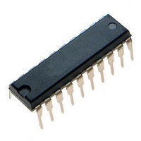
MCR908JK1ECPE Freescale Semiconductor, MCR908JK1ECPE Datasheet - Page 100

MCR908JK1ECPE
Manufacturer Part Number
MCR908JK1ECPE
Description
IC MCU 1.5K FLASH 8MHZ 20-DIP
Manufacturer
Freescale Semiconductor
Series
HC08r
Datasheet
1.MC908JK1ECDWE.pdf
(180 pages)
Specifications of MCR908JK1ECPE
Core Processor
HC08
Core Size
8-Bit
Speed
8MHz
Peripherals
LED, LVD, POR, PWM
Number Of I /o
14
Program Memory Size
1.5KB (1.5K x 8)
Program Memory Type
FLASH
Ram Size
128 x 8
Voltage - Supply (vcc/vdd)
2.7 V ~ 3.3 V
Data Converters
A/D 12x8b
Oscillator Type
External
Operating Temperature
-40°C ~ 85°C
Package / Case
20-DIP (0.300", 7.62mm)
Processor Series
HC08JK
Core
HC08
Data Bus Width
8 bit
Data Ram Size
128 B
Maximum Clock Frequency
8 MHz
Number Of Programmable I/os
15
Number Of Timers
2
Maximum Operating Temperature
+ 85 C
Mounting Style
Through Hole
Development Tools By Supplier
FSICEBASE, DEMO908JL16E, M68CBL05CE
Minimum Operating Temperature
- 40 C
On-chip Adc
8 bit, 12 Channel
Lead Free Status / RoHS Status
Lead free / RoHS Compliant
Eeprom Size
-
Connectivity
-
Lead Free Status / Rohs Status
Details
Available stocks
Company
Part Number
Manufacturer
Quantity
Price
Company:
Part Number:
MCR908JK1ECPE
Manufacturer:
Freescale Semiconductor
Quantity:
135
- Current page: 100 of 180
- Download datasheet (3Mb)
Analog-to-Digital Converter (ADC)
9.5.2 Stop Mode
The ADC module is inactive after the execution of a STOP instruction. Any pending conversion is aborted.
ADC conversions resume when the MCU exits stop mode. Allow one conversion cycle to stabilize the
analog circuitry before attempting a new ADC conversion after exiting stop mode.
9.6 I/O Signals
The ADC module has 12 channels that are shared with I/O port B and port D.
9.6.1 ADC Voltage In (ADCVIN)
ADCVIN is the input voltage signal from one of the 12 ADC channels to the ADC module.
9.7 I/O Registers
These I/O registers control and monitor ADC operation:
9.7.1 ADC Status and Control Register
The following paragraphs describe the function of the ADC status and control register.
COCO — Conversions Complete Bit
AIEN — ADC Interrupt Enable Bit
100
•
•
•
When the AIEN bit is a 0, the COCO is a read-only bit which is set each time a conversion is completed.
This bit is cleared whenever the ADC status and control register is written or whenever the ADC data
register is read. Reset clears this bit.
When the AIEN bit is a 1 (CPU interrupt enabled), the COCO is a read-only bit, and will always be 0
when read.
When this bit is set, an interrupt is generated at the end of an ADC conversion. The interrupt signal is
cleared when the data register is read or the status/control register is written. Reset clears the AIEN bit.
1 = Conversion completed (AIEN = 0)
0 = Conversion not completed (AIEN = 0)
1 = ADC interrupt enabled
0 = ADC interrupt disabled
ADC status and control register (ADSCR)
ADC data register (ADR)
ADC clock register (ADICLK)
Address:
Reset:
Read:
Write:
$003C
COCO
Figure 9-3. ADC Status and Control Register (ADSCR)
Bit 7
0
= Unimplemented
AIEN
MC68HC908JL3E Family Data Sheet, Rev. 4
6
0
ADCO
5
0
ADCH4
4
1
ADCH3
3
1
ADCH2
2
1
ADCH1
1
1
Freescale Semiconductor
ADCH0
Bit 0
1
Related parts for MCR908JK1ECPE
Image
Part Number
Description
Manufacturer
Datasheet
Request
R
Part Number:
Description:
Manufacturer:
Freescale Semiconductor, Inc
Datasheet:
Part Number:
Description:
Manufacturer:
Freescale Semiconductor, Inc
Datasheet:
Part Number:
Description:
Manufacturer:
Freescale Semiconductor, Inc
Datasheet:
Part Number:
Description:
Manufacturer:
Freescale Semiconductor, Inc
Datasheet:
Part Number:
Description:
Manufacturer:
Freescale Semiconductor, Inc
Datasheet:
Part Number:
Description:
Manufacturer:
Freescale Semiconductor, Inc
Datasheet:
Part Number:
Description:
Manufacturer:
Freescale Semiconductor, Inc
Datasheet:
Part Number:
Description:
Manufacturer:
Freescale Semiconductor, Inc
Datasheet:
Part Number:
Description:
Manufacturer:
Freescale Semiconductor, Inc
Datasheet:
Part Number:
Description:
Manufacturer:
Freescale Semiconductor, Inc
Datasheet:
Part Number:
Description:
Manufacturer:
Freescale Semiconductor, Inc
Datasheet:
Part Number:
Description:
Manufacturer:
Freescale Semiconductor, Inc
Datasheet:
Part Number:
Description:
Manufacturer:
Freescale Semiconductor, Inc
Datasheet:
Part Number:
Description:
Manufacturer:
Freescale Semiconductor, Inc
Datasheet:
Part Number:
Description:
Manufacturer:
Freescale Semiconductor, Inc
Datasheet:


