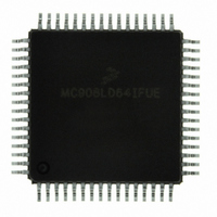
MC908LD64IFUE Freescale Semiconductor, MC908LD64IFUE Datasheet - Page 285

MC908LD64IFUE
Manufacturer Part Number
MC908LD64IFUE
Description
IC MCU 8BIT FOR LCD 64-QFP
Manufacturer
Freescale Semiconductor
Series
HC08r
Datasheet
1.MC908LD64IFUE.pdf
(362 pages)
Specifications of MC908LD64IFUE
Core Processor
HC08
Core Size
8-Bit
Speed
6MHz
Connectivity
I²C, USB
Peripherals
OSD, POR, PWM
Number Of I /o
39
Program Memory Size
60KB (60K x 8)
Program Memory Type
FLASH
Ram Size
2K x 8
Voltage - Supply (vcc/vdd)
3 V ~ 3.6 V
Data Converters
A/D 6x8b
Oscillator Type
Internal
Operating Temperature
0°C ~ 85°C
Package / Case
64-QFP
Processor Series
HC08LD
Core
HC08
Data Bus Width
8 bit
Data Ram Size
2 KB
Interface Type
I2C, USB
Maximum Clock Frequency
6 MHz
Number Of Programmable I/os
39
Number Of Timers
2
Maximum Operating Temperature
+ 85 C
Mounting Style
SMD/SMT
Development Tools By Supplier
FSICEBASE, M68CBL05CE
Minimum Operating Temperature
0 C
On-chip Adc
8 bit, 6 Channel
Lead Free Status / RoHS Status
Lead free / RoHS Compliant
Eeprom Size
-
Lead Free Status / Rohs Status
Details
Available stocks
Company
Part Number
Manufacturer
Quantity
Price
Company:
Part Number:
MC908LD64IFUE
Manufacturer:
Freescale Semiconductor
Quantity:
10 000
Part Number:
MC908LD64IFUE
Manufacturer:
FREESCALE
Quantity:
20 000
- Current page: 285 of 362
- Download datasheet (2Mb)
18.8.3.2 Vertical Delay Control Register
MC68HC908LD64
Freescale Semiconductor
—
Rev. 3.0
W_SHD — Shadow on Window
R, G, B — Background Window Color
Row 15, Column 12:
VERTD —þVertical Delay
15
Set this bit to activate the window shadowing. When the window is
active, the right M pixels and lower N horizontal scan lines will output
shadowing. The M, N, and color of window shadow is defined in the
frame control registers located at row 15, column 16, 17, 18, and 19.
See
These bits define the color of the background window.
These bits define the vertical starting position. The 8-bit gives 256
steps, with each step increment of four horizontal lines for each field.
Its value cannot be zero at anytime. In order to avoid screen
misalignment, the value of VERTD is decided by the last OSD line not
over the next leading edge of PVSYNC.
1 = Background window shadow enabled
0 = Background window shadow disabled
14
18.8.3.5 Frame Control Registers
Row start address
Row end address
13
On-Screen Display (OSD)
12
11
Column start address
10
M
9
WINDOW AREA
8
MSB
7
SHADOW
6
Column end address
5
for details.
M
4
VERTD
M and N are defined in the
frame control registers located
at row 15, column 16 and 17.
On-Screen Display (OSD)
3
N
N
2
OSD Registers
1
Data Sheet
LSB
0
285
Related parts for MC908LD64IFUE
Image
Part Number
Description
Manufacturer
Datasheet
Request
R
Part Number:
Description:
Manufacturer:
Freescale Semiconductor, Inc
Datasheet:
Part Number:
Description:
Manufacturer:
Freescale Semiconductor, Inc
Datasheet:
Part Number:
Description:
Manufacturer:
Freescale Semiconductor, Inc
Datasheet:
Part Number:
Description:
Manufacturer:
Freescale Semiconductor, Inc
Datasheet:
Part Number:
Description:
Manufacturer:
Freescale Semiconductor, Inc
Datasheet:
Part Number:
Description:
Manufacturer:
Freescale Semiconductor, Inc
Datasheet:
Part Number:
Description:
Manufacturer:
Freescale Semiconductor, Inc
Datasheet:
Part Number:
Description:
Manufacturer:
Freescale Semiconductor, Inc
Datasheet:
Part Number:
Description:
Manufacturer:
Freescale Semiconductor, Inc
Datasheet:
Part Number:
Description:
Manufacturer:
Freescale Semiconductor, Inc
Datasheet:
Part Number:
Description:
Manufacturer:
Freescale Semiconductor, Inc
Datasheet:
Part Number:
Description:
Manufacturer:
Freescale Semiconductor, Inc
Datasheet:
Part Number:
Description:
Manufacturer:
Freescale Semiconductor, Inc
Datasheet:
Part Number:
Description:
Manufacturer:
Freescale Semiconductor, Inc
Datasheet:
Part Number:
Description:
Manufacturer:
Freescale Semiconductor, Inc
Datasheet:


