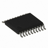
ATTINY167-15XD Atmel, ATTINY167-15XD Datasheet - Page 181

ATTINY167-15XD
Manufacturer Part Number
ATTINY167-15XD
Description
MCU AVR 16K FLASH 15MHZ 20-TSSOP
Manufacturer
Atmel
Series
AVR® ATtinyr
Datasheet
1.ATTINY167-15MD.pdf
(283 pages)
Specifications of ATTINY167-15XD
Core Processor
AVR
Core Size
8-Bit
Speed
16MHz
Connectivity
I²C, LIN, SPI, UART/USART, USI
Peripherals
Brown-out Detect/Reset, POR, PWM, Temp Sensor, WDT
Number Of I /o
16
Program Memory Size
16KB (8K x 16)
Program Memory Type
FLASH
Eeprom Size
512 x 8
Ram Size
512 x 8
Voltage - Supply (vcc/vdd)
2.7 V ~ 5.5 V
Data Converters
A/D 11x10b
Oscillator Type
Internal
Operating Temperature
-40°C ~ 150°C
Package / Case
20-TSSOP
Processor Series
ATTINY1x
Core
AVR8
Data Bus Width
8 bit
Data Ram Size
512 B
Maximum Clock Frequency
16 MHz
Maximum Operating Temperature
+ 85 C
Mounting Style
SMD/SMT
3rd Party Development Tools
EWAVR, EWAVR-BL
Development Tools By Supplier
ATAVRDRAGON, ATSTK500, ATSTK600, ATAVRISP2, ATAVRONEKIT
Minimum Operating Temperature
- 40 C
For Use With
ATSTK600-SOIC - STK600 SOCKET/ADAPTER FOR SOIC
Lead Free Status / RoHS Status
Lead free / RoHS Compliant
- Current page: 181 of 283
- Download datasheet (5Mb)
15.6.1
7728G–AVR–06/10
LIN Control Register - LINCR
• Bit 7 - LSWRES: Software Reset
• Bit 6 - LIN13: LIN 1.3 mode
• Bit 5:4 - LCONF[1:0]: Configuration
• Bit 3 - LENA: Enable
• Bit 2:0 - LCMD[2..0]: Command and mode
Initial Value
Read/Write
Bit
– 0 = No action,
– 1 = Software reset (this bit is self-reset at the end of the reset procedure).
– 0 = LIN 2.1 (default),
– 1 = LIN 1.3.
a. LIN mode (default = 00):
– 00 = LIN Standard configuration (listen mode “off”, CRC “on” & Frame_Time_Out
– 01 = No CRC, No Frame_Time_Out (listen mode “off”),
– 10 = No Frame_Time_Out (listen mode “off” & CRC “on”),
– 11 = Listening mode (CRC “on” & Frame_Time_Out “on”).
b. UART mode (default = 00):
– 00 = 8-bit, no parity (listen mode “off”),
– 01 = 8-bit, even parity (listen mode “off”),
– 10 = 8-bit, odd parity (listen mode “off”),
– 11 = Listening mode, 8-bit, no parity.
– 0 = Disable (both LIN and UART modes),
– 1 = Enable (both LIN and UART modes).
– 000 = LIN Rx Header - LIN abort,
– 001 = LIN Tx Header,
– 010 = LIN Rx Response,
– 011 = LIN Tx Response,
– 100 = UART Rx & Tx Byte disable,
– 11x = UART Rx Byte enable,
– 1x1 = UART Tx Byte enable.
The command is only available if LENA is set.
“on”,
LSWRES
R/W
7
0
LIN13
R/W
6
0
LCONF1
R/W
5
0
LCONF0
R/W
4
0
LENA
R/W
3
0
ATtiny87/ATtiny167
LCMD2
R/W
2
0
LCMD1
R/W
1
0
LCMD0
R/W
0
0
LINCR
181
Related parts for ATTINY167-15XD
Image
Part Number
Description
Manufacturer
Datasheet
Request
R

Part Number:
Description:
Manufacturer:
Atmel Corporation
Datasheet:

Part Number:
Description:
Manufacturer:
Atmel Corporation
Datasheet:

Part Number:
Description:
MCU AVR 16K FLASH 15MHZ 32-QFN
Manufacturer:
Atmel
Datasheet:

Part Number:
Description:
IC MCU AVR 16K FLASH 20TSSOP
Manufacturer:
Atmel
Datasheet:

Part Number:
Description:
MCU AVR 16K FLASH 15MHZ 32-QFN
Manufacturer:
Atmel
Datasheet:

Part Number:
Description:
MCU AVR 16K FLASH 15MHZ 20-SOIC
Manufacturer:
Atmel
Datasheet:

Part Number:
Description:
MCU AVR 16K FLASH 15MHZ 20-TSSOP
Manufacturer:
Atmel
Datasheet:

Part Number:
Description:
IC MCU AVR 16K FLASH 20SOIC
Manufacturer:
Atmel
Datasheet:


