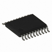
ATTINY167-15XD Atmel, ATTINY167-15XD Datasheet - Page 30

ATTINY167-15XD
Manufacturer Part Number
ATTINY167-15XD
Description
MCU AVR 16K FLASH 15MHZ 20-TSSOP
Manufacturer
Atmel
Series
AVR® ATtinyr
Datasheet
1.ATTINY167-15MD.pdf
(283 pages)
Specifications of ATTINY167-15XD
Core Processor
AVR
Core Size
8-Bit
Speed
16MHz
Connectivity
I²C, LIN, SPI, UART/USART, USI
Peripherals
Brown-out Detect/Reset, POR, PWM, Temp Sensor, WDT
Number Of I /o
16
Program Memory Size
16KB (8K x 16)
Program Memory Type
FLASH
Eeprom Size
512 x 8
Ram Size
512 x 8
Voltage - Supply (vcc/vdd)
2.7 V ~ 5.5 V
Data Converters
A/D 11x10b
Oscillator Type
Internal
Operating Temperature
-40°C ~ 150°C
Package / Case
20-TSSOP
Processor Series
ATTINY1x
Core
AVR8
Data Bus Width
8 bit
Data Ram Size
512 B
Maximum Clock Frequency
16 MHz
Maximum Operating Temperature
+ 85 C
Mounting Style
SMD/SMT
3rd Party Development Tools
EWAVR, EWAVR-BL
Development Tools By Supplier
ATAVRDRAGON, ATSTK500, ATSTK600, ATAVRISP2, ATAVRONEKIT
Minimum Operating Temperature
- 40 C
For Use With
ATSTK600-SOIC - STK600 SOCKET/ADAPTER FOR SOIC
Lead Free Status / RoHS Status
Lead free / RoHS Compliant
- Current page: 30 of 283
- Download datasheet (5Mb)
4.2.6
30
ATtiny87/ATtiny167
External Clock
Figure 4-3.
When this oscillator is selected, start-up times are determined by the SUT fuses or by CSUT
field as shown in
Table 4-8.
Notes:
To drive the device from this external clock source, CLKI should be driven as shown in
4-4. To run the device on an external clock, the CKSEL Fuses or CSEL field must be pro-
grammed as shown in
Figure 4-4.
When this clock source is selected, start-up times are determined by the SUT Fuses or CSUT
field as shown in
This external clock can be used by the asynchronous timer if the high or low frequency Crystal
Oscillator is not running
timer is then able to enable this input.
CSUT1..0
SUT1..0
00
01
10
11
1. Flash Fuse bits.
2. CLKSELR register bits.
3. These options should only be used if frequency stability at start-up is not important for the
(1)
(2)
application.
Low-frequency Crystal Oscillator Connections
Start-up Times for the Low Frequency Crystal Oscillator Clock Selection
External Clock Drive Configuration
Start-up Time from
Power-down/save
Table
Table
32K (32768) CK
1K (1024) CK
1K (1024) CK
Table 4-1 on page
4-8.
4-9.
(See ”Enable/Disable Clock Source” on page
12-22 pF capacitors may be necessary if parasitic
impedance (pads, wires & PCB) is very low.
(3)
(3)
External
32.768 KHz
Signal
Clock
~
C1=12-22 pF
C2=12-22 pF
Additional Delay from
Reset (Vcc = 5.0V)
25.
4.1 ms
65 ms
65 ms
Reserved
(XTAL2)
(XTAL1)
(CLKO)
CLKI
GND
XTAL2
XTAL1
GND
Recommended usage
Fast rising power or BOD enabled
Slowly rising power
Stable frequency at start-up
32.). The asynchronous
7728G–AVR–06/10
Figure
Related parts for ATTINY167-15XD
Image
Part Number
Description
Manufacturer
Datasheet
Request
R

Part Number:
Description:
Manufacturer:
Atmel Corporation
Datasheet:

Part Number:
Description:
Manufacturer:
Atmel Corporation
Datasheet:

Part Number:
Description:
MCU AVR 16K FLASH 15MHZ 32-QFN
Manufacturer:
Atmel
Datasheet:

Part Number:
Description:
IC MCU AVR 16K FLASH 20TSSOP
Manufacturer:
Atmel
Datasheet:

Part Number:
Description:
MCU AVR 16K FLASH 15MHZ 32-QFN
Manufacturer:
Atmel
Datasheet:

Part Number:
Description:
MCU AVR 16K FLASH 15MHZ 20-SOIC
Manufacturer:
Atmel
Datasheet:

Part Number:
Description:
MCU AVR 16K FLASH 15MHZ 20-TSSOP
Manufacturer:
Atmel
Datasheet:

Part Number:
Description:
IC MCU AVR 16K FLASH 20SOIC
Manufacturer:
Atmel
Datasheet:


