OM13006,598 NXP Semiconductors, OM13006,598 Datasheet - Page 35
OM13006,598
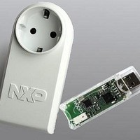
Manufacturer Part Number
OM13006,598
Description
BOARD EVAL EM773 METER EU PLUG
Manufacturer
NXP Semiconductors
Type
Other Power Managementr
Specifications of OM13006,598
Design Resources
Plug Meter Schematics, Gerber Files USB Dongle Schematics, Gerber Files
Main Purpose
Power Management, Energy/Power Meter
Embedded
Yes, MCU, 32-Bit
Utilized Ic / Part
EM773FHN33,551
Interface Type
USB
Maximum Operating Temperature
+ 150 C
Operating Supply Voltage
1.8 V to 3.6 V
Product
Power Management Development Tools
Lead Free Status / RoHS Status
Lead free / RoHS Compliant
Primary Attributes
-
Secondary Attributes
-
Lead Free Status / Rohs Status
Lead free / RoHS Compliant
For Use With/related Products
EM773, OL2381
Other names
568-6681


NXP Semiconductors
3.9 System PLL functional description
UM10415
User manual
Fig 4.
sys_osc_clk
irc_osc_clk
SYSPLLCLKSEL
System PLL block diagram
10. Use the ARM WFI instruction to enter Deep-sleep mode.
The EM773 uses the system PLL to create the clocks for the core and peripherals.
The block diagram of this PLL is shown in
to 25 MHz. The input clock is fed directly to the Phase-Frequency Detector (PFD). This
block compares the phase and frequency of its inputs, and generates a control signal
when phase and/ or frequency do not match. The loop filter filters these control signals
and drives the current controlled oscillator (CCO), which generates the main clock and
optionally two additional phases. The CCO frequency range is 156 MHz to
320 MHz.These clocks are either divided by 2×P by the programmable post divider to
1. Configure the port pin as match output in the IOCONFIG block. Select from pins
2. In the corresponding counter/timer, set the match value, and configure the match
3. Select the watchdog oscillator to run in Deep-sleep mode in the PDSLEEPCFG
4. Switch the clock source to the watchdog oscillator in the MAINCLKSEL register
5. Enable the pin, configure its edge detect function, and reset the start logic in the start
6. Disable all other peripherals in the SYSAHBCLKCTRL register.
7. Ensure that the DPDEN bit in the PCON register is set to zero
8. Write one to the SLEEPDEEP bit in the ARM Cortex-M0 SCR register
9. Start the counter/timer.
PIO0_1 or PIO0_8 to PIO0_11, which are inputs to the start logic and also hold a
match output function.
output for the selected pin.
register.
(Table
logic registers
PFD
14) and ensure the watchdog oscillator is powered in the PDRUNCFG register.
analog section
DETECT
All information provided in this document is subject to legal disclaimers.
LOCK
MSEL<4:0>
/M
pd
(Table 30
cd
5
Rev. 1 — 10 September 2010
pd
to
LOCK
Table
33), and enable the interrupt in the NVIC.
Figure
Chapter 3: EM773 System configuration
PSEL<1:0>
4. The input frequency range is 10 MHz
2
/2P
pd
cd
(Table
UM10415
© NXP B.V. 2010. All rights reserved.
43).
(Table
FCLKOUT
250).
35 of 13
Related parts for OM13006,598
Image
Part Number
Description
Manufacturer
Datasheet
Request
R

Part Number:
Description:
NXP Semiconductors designed the LPC2420/2460 microcontroller around a 16-bit/32-bitARM7TDMI-S CPU core with real-time debug interfaces that include both JTAG andembedded trace
Manufacturer:
NXP Semiconductors
Datasheet:

Part Number:
Description:
NXP Semiconductors designed the LPC2458 microcontroller around a 16-bit/32-bitARM7TDMI-S CPU core with real-time debug interfaces that include both JTAG andembedded trace
Manufacturer:
NXP Semiconductors
Datasheet:
Part Number:
Description:
NXP Semiconductors designed the LPC2468 microcontroller around a 16-bit/32-bitARM7TDMI-S CPU core with real-time debug interfaces that include both JTAG andembedded trace
Manufacturer:
NXP Semiconductors
Datasheet:
Part Number:
Description:
NXP Semiconductors designed the LPC2470 microcontroller, powered by theARM7TDMI-S core, to be a highly integrated microcontroller for a wide range ofapplications that require advanced communications and high quality graphic displays
Manufacturer:
NXP Semiconductors
Datasheet:
Part Number:
Description:
NXP Semiconductors designed the LPC2478 microcontroller, powered by theARM7TDMI-S core, to be a highly integrated microcontroller for a wide range ofapplications that require advanced communications and high quality graphic displays
Manufacturer:
NXP Semiconductors
Datasheet:
Part Number:
Description:
The Philips Semiconductors XA (eXtended Architecture) family of 16-bit single-chip microcontrollers is powerful enough to easily handle the requirements of high performance embedded applications, yet inexpensive enough to compete in the market for hi
Manufacturer:
NXP Semiconductors
Datasheet:
Part Number:
Description:
The XA-S3 device is a member of Philips Semiconductors? XA(eXtended Architecture) family of high performance 16-bitsingle-chip microcontrollers
Manufacturer:
NXP Semiconductors
Datasheet:

Part Number:
Description:
The NXP BlueStreak LH75401/LH75411 family consists of two low-cost 16/32-bit System-on-Chip (SoC) devices
Manufacturer:
NXP Semiconductors
Datasheet:
Part Number:
Description:
The NXP LPC3130/3131 combine an 180 MHz ARM926EJ-S CPU core, high-speed USB2
Manufacturer:
NXP Semiconductors
Datasheet:
Part Number:
Description:
The NXP LPC3141 combine a 270 MHz ARM926EJ-S CPU core, High-speed USB 2
Manufacturer:
NXP Semiconductors
Part Number:
Description:
The NXP LPC3143 combine a 270 MHz ARM926EJ-S CPU core, High-speed USB 2
Manufacturer:
NXP Semiconductors

Part Number:
Description:
The NXP LPC3152 combines an 180 MHz ARM926EJ-S CPU core, High-speed USB 2
Manufacturer:
NXP Semiconductors
Part Number:
Description:
The NXP LPC3154 combines an 180 MHz ARM926EJ-S CPU core, High-speed USB 2
Manufacturer:
NXP Semiconductors

Part Number:
Description:
Standard level N-channel enhancement mode Field-Effect Transistor (FET) in a plastic package using NXP High-Performance Automotive (HPA) TrenchMOS technology
Manufacturer:
NXP Semiconductors
Datasheet: