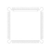
MC68HC16Z1CEH16 Freescale Semiconductor, MC68HC16Z1CEH16 Datasheet - Page 205

MC68HC16Z1CEH16
Manufacturer Part Number
MC68HC16Z1CEH16
Description
IC MCU 16BIT 16MHZ 132-PQFP
Manufacturer
Freescale Semiconductor
Series
HC16r
Specifications of MC68HC16Z1CEH16
Core Processor
CPU16
Core Size
16-Bit
Speed
16MHz
Connectivity
EBI/EMI, SCI, SPI
Peripherals
POR, PWM, WDT
Number Of I /o
16
Program Memory Type
ROMless
Ram Size
1K x 8
Voltage - Supply (vcc/vdd)
2.7 V ~ 5.5 V
Data Converters
A/D 8x10b
Oscillator Type
Internal
Operating Temperature
-40°C ~ 85°C
Package / Case
132-QFP
Processor Series
HC16Z
Core
CPU16
Data Bus Width
16 bit
Controller Family/series
68HC16
No. Of I/o's
26
Ram Memory Size
1KB
Cpu Speed
16MHz
No. Of Timers
2
Embedded Interface Type
QSPI, SCI
Rohs Compliant
Yes
Package
132PQFP
Family Name
HC16
Maximum Speed
16 MHz
Operating Supply Voltage
3.3|5 V
Number Of Programmable I/os
16
On-chip Adc
8-chx10-bit
Number Of Timers
11
Data Ram Size
1 KB
Interface Type
SCI, SPI, UART
Maximum Clock Frequency
16 MHz
Maximum Operating Temperature
+ 85 C
Mounting Style
SMD/SMT
Minimum Operating Temperature
- 40 C
Lead Free Status / RoHS Status
Lead free / RoHS Compliant
Eeprom Size
-
Program Memory Size
-
Lead Free Status / Rohs Status
Lead free / RoHS Compliant
Available stocks
Company
Part Number
Manufacturer
Quantity
Price
Company:
Part Number:
MC68HC16Z1CEH16
Manufacturer:
Freescale Semiconductor
Quantity:
10 000
Part Number:
MC68HC16Z1CEH16
Manufacturer:
FREESCALE
Quantity:
20 000
- Current page: 205 of 500
- Download datasheet (6Mb)
8.8.5 Analog Input Considerations
M68HC16 Z SERIES
USER’S MANUAL
The current out of the pin (I
equation:
where:
The current into (I
sitic bipolar transistor (1/K
One way to minimize the impact of stress conditions on the ADC is to apply voltage
limiting circuits such as diodes to supply and ground. However, leakage from such cir-
cuits and the potential influence on the sampled voltage to be converted must be con-
sidered. Refer to
Another method for minimizing the impact of stress conditions on the ADC is to stra-
tegically allocate ADC inputs so that the lower accuracy inputs are adjacent to the in-
puts most likely to see stress conditions.
Finally, suitable source impedances should be selected to meet design goals and min-
imize the effect of stress conditions.
The source impedance of the analog signal to be measured and any intermediate fil-
tering should be considered whether external multiplexing is used or not.
shows the connection of eight typical analog signal sources to one ADC analog input
pin through a separate multiplexer chip. Also, an example of an analog signal source
connected directly to a ADC analog input channel is displayed.
Figure 8-8 Voltage Limiting Diodes in a Negative Stress Circuit
V
V
APPENDIX A ELECTRICAL
R
channel)
STRESS
BE
STRESS
EXTERNAL VOLTAGE
= Parasitic bipolar base/emitter voltage (refer to V
Figure
= Adjustable voltage source
IN
= Source impedance (10K resistor in
) the neighboring pin is determined by the 1/K
Freescale Semiconductor, Inc.
For More Information On This Product,
ANALOG-TO-DIGITAL CONVERTER
8-8.
N
‹‹1).
OUT
Go to: www.freescale.com
) under negative stress is determined by the following
I
OUT
kR
=
CHARACTERISTICS)
VDD
VSS
------------------------------------------ -
V
STRESS
R
STRESS
R
–
V
BE
Figure 8-7
TO DEVICE
NEGCLAMP
N
(Gain) of the para-
on stressed
in
Figure 8-9
ADC NEG STRESS CONN
8-19
Related parts for MC68HC16Z1CEH16
Image
Part Number
Description
Manufacturer
Datasheet
Request
R
Part Number:
Description:
Manufacturer:
Freescale Semiconductor, Inc
Datasheet:
Part Number:
Description:
Manufacturer:
Freescale Semiconductor, Inc
Datasheet:
Part Number:
Description:
Manufacturer:
Freescale Semiconductor, Inc
Datasheet:
Part Number:
Description:
Manufacturer:
Freescale Semiconductor, Inc
Datasheet:
Part Number:
Description:
Manufacturer:
Freescale Semiconductor, Inc
Datasheet:
Part Number:
Description:
Manufacturer:
Freescale Semiconductor, Inc
Datasheet:
Part Number:
Description:
Manufacturer:
Freescale Semiconductor, Inc
Datasheet:
Part Number:
Description:
Manufacturer:
Freescale Semiconductor, Inc
Datasheet:
Part Number:
Description:
Manufacturer:
Freescale Semiconductor, Inc
Datasheet:
Part Number:
Description:
Manufacturer:
Freescale Semiconductor, Inc
Datasheet:
Part Number:
Description:
Manufacturer:
Freescale Semiconductor, Inc
Datasheet:
Part Number:
Description:
Manufacturer:
Freescale Semiconductor, Inc
Datasheet:
Part Number:
Description:
Manufacturer:
Freescale Semiconductor, Inc
Datasheet:
Part Number:
Description:
Manufacturer:
Freescale Semiconductor, Inc
Datasheet:
Part Number:
Description:
Manufacturer:
Freescale Semiconductor, Inc
Datasheet:


