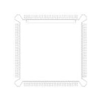
MC68HC16Z1CEH16 Freescale Semiconductor, MC68HC16Z1CEH16 Datasheet - Page 346

MC68HC16Z1CEH16
Manufacturer Part Number
MC68HC16Z1CEH16
Description
IC MCU 16BIT 16MHZ 132-PQFP
Manufacturer
Freescale Semiconductor
Series
HC16r
Specifications of MC68HC16Z1CEH16
Core Processor
CPU16
Core Size
16-Bit
Speed
16MHz
Connectivity
EBI/EMI, SCI, SPI
Peripherals
POR, PWM, WDT
Number Of I /o
16
Program Memory Type
ROMless
Ram Size
1K x 8
Voltage - Supply (vcc/vdd)
2.7 V ~ 5.5 V
Data Converters
A/D 8x10b
Oscillator Type
Internal
Operating Temperature
-40°C ~ 85°C
Package / Case
132-QFP
Processor Series
HC16Z
Core
CPU16
Data Bus Width
16 bit
Controller Family/series
68HC16
No. Of I/o's
26
Ram Memory Size
1KB
Cpu Speed
16MHz
No. Of Timers
2
Embedded Interface Type
QSPI, SCI
Rohs Compliant
Yes
Package
132PQFP
Family Name
HC16
Maximum Speed
16 MHz
Operating Supply Voltage
3.3|5 V
Number Of Programmable I/os
16
On-chip Adc
8-chx10-bit
Number Of Timers
11
Data Ram Size
1 KB
Interface Type
SCI, SPI, UART
Maximum Clock Frequency
16 MHz
Maximum Operating Temperature
+ 85 C
Mounting Style
SMD/SMT
Minimum Operating Temperature
- 40 C
Lead Free Status / RoHS Status
Lead free / RoHS Compliant
Eeprom Size
-
Program Memory Size
-
Lead Free Status / Rohs Status
Lead free / RoHS Compliant
Available stocks
Company
Part Number
Manufacturer
Quantity
Price
Company:
Part Number:
MC68HC16Z1CEH16
Manufacturer:
Freescale Semiconductor
Quantity:
10 000
Part Number:
MC68HC16Z1CEH16
Manufacturer:
FREESCALE
Quantity:
20 000
- Current page: 346 of 500
- Download datasheet (6Mb)
A-62
Num
10
11
12
NOTES:
1
2
3
4
5
6
7
8
9
1. Below disruptive current conditions, a stressed channel will store the maximum conversion value for analog
2. Input signals with large slew rates or high frequency noise components cannot be converted accurately. These
3. Exceeding limit may cause conversion error on stressed channels and on unstressed channels. Transitions
4. Input must be current limited to the value specified. To determine the value of the required current-limiting re-
5. This parameter is periodically sampled rather than 100% tested.
6. Applies to single pin only.
7. The values of external system components can change the maximum input current value, and affect operation.
8. Current coupling is the ratio of the current induced from overvoltage (positive or negative, through an external
inputs greater than V
V
disruptive conditions.
signals also interfere with conversion of other channels.
within the limit do not affect device reliability or cause permanent damage.
sistor, calculate resistance values using positive and negative clamp values, then use the larger of the calcu-
lated values.
A voltage drop may occur across the external source impedances of the adjacent pins, impacting conversions
on these adjacent pins. The actual maximum may need to be determined by testing the complete design.
series coupling resistor), divided by the current induced on adjacent pins. A voltage drop may occur across the
external source impedances of the adjacent pins, impacting conversions on these adjacent pins.
Analog Supply
Internal Digital Supply, with reference to V
Reference Supply, with reference to V
V
V
V
V
V
Disruptive Input Current
Positive Overvoltage Current Coupling Ratio
Negative Overvoltage Current Coupling Ratio
Maximum Input Current
DDA
SS
DD
REF
RH
RL
V
V
V
V
NEGCLAMP
POSCLAMP
NEGCLAMP
POSCLAMP
Differential Voltage
to V
Differential Voltage
to V
Differential Voltage
and V
SSA
DDA
RL
Differential Voltage
Differential Voltage
–0.3 V
–0.3 V
8 V
8 V
V
SSA
RH
due to the presence of the sample amplifier. Other channels are not affected by non-
Freescale Semiconductor, Inc.
and the minimum conversion value for inputs less than V
3,4,6
1
For More Information On This Product,
,
Table A-32 ADC Maximum Ratings
Parameter
2
,
3
,
ELECTRICAL CHARACTERISTICS
4
,
5
,
Go to: www.freescale.com
6
,
7
SSI
SSI
1,5,6,8
1,5,6,8
V
V
V
V
V
V
DDI
SSI
Symbol
RH
RL
RH
RH
V
V
I
I
K
K
DDA
–V
–V
MA
NA
DDI
–V
–V
, V
–V
N
P
DDA
SSA
SSA
DDA
RL
RL
RL
. This assumes that V
–500
2000
–0.3
–0.3
–0.3
–0.1
–6.5
–6.5
–6.5
–6.5
Min
500
–25
M68HC16 Z SERIES
USER’S MANUAL
Max
500
6.5
6.5
6.5
0.1
6.5
6.5
6.5
6.5
25
—
—
Unit
mA
RH
—
—
V
V
V
V
V
V
V
V
A
Related parts for MC68HC16Z1CEH16
Image
Part Number
Description
Manufacturer
Datasheet
Request
R
Part Number:
Description:
Manufacturer:
Freescale Semiconductor, Inc
Datasheet:
Part Number:
Description:
Manufacturer:
Freescale Semiconductor, Inc
Datasheet:
Part Number:
Description:
Manufacturer:
Freescale Semiconductor, Inc
Datasheet:
Part Number:
Description:
Manufacturer:
Freescale Semiconductor, Inc
Datasheet:
Part Number:
Description:
Manufacturer:
Freescale Semiconductor, Inc
Datasheet:
Part Number:
Description:
Manufacturer:
Freescale Semiconductor, Inc
Datasheet:
Part Number:
Description:
Manufacturer:
Freescale Semiconductor, Inc
Datasheet:
Part Number:
Description:
Manufacturer:
Freescale Semiconductor, Inc
Datasheet:
Part Number:
Description:
Manufacturer:
Freescale Semiconductor, Inc
Datasheet:
Part Number:
Description:
Manufacturer:
Freescale Semiconductor, Inc
Datasheet:
Part Number:
Description:
Manufacturer:
Freescale Semiconductor, Inc
Datasheet:
Part Number:
Description:
Manufacturer:
Freescale Semiconductor, Inc
Datasheet:
Part Number:
Description:
Manufacturer:
Freescale Semiconductor, Inc
Datasheet:
Part Number:
Description:
Manufacturer:
Freescale Semiconductor, Inc
Datasheet:
Part Number:
Description:
Manufacturer:
Freescale Semiconductor, Inc
Datasheet:


