MC68EN360CAI25L Freescale Semiconductor, MC68EN360CAI25L Datasheet - Page 533
MC68EN360CAI25L
Manufacturer Part Number
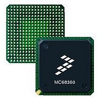
MC68EN360CAI25L
Description
IC MPU QUICC 25MHZ 240-FQFP
Manufacturer
Freescale Semiconductor
Series
MC68000r
Datasheets
1.MC68EN302AG20BT.pdf
(8 pages)
2.MC68EN360VR25L.pdf
(14 pages)
3.MC68EN360VR25L.pdf
(2 pages)
4.MC68EN360CAI25L.pdf
(962 pages)
Specifications of MC68EN360CAI25L
Processor Type
M683xx 32-Bit
Speed
25MHz
Voltage
5V
Mounting Type
Surface Mount
Package / Case
240-FQFP
Core Size
32 Bit
Cpu Speed
25MHz
Embedded Interface Type
SCP, TDM
Digital Ic Case Style
FQFP
No. Of Pins
240
Supply Voltage Range
4.75V To 5.25V
Rohs Compliant
Yes
Family Name
M68xxx
Device Core
ColdFire
Device Core Size
32b
Frequency (max)
25MHz
Instruction Set Architecture
RISC
Supply Voltage 1 (typ)
5V
Operating Supply Voltage (max)
5.25V
Operating Supply Voltage (min)
4.75V
Operating Temp Range
-40C to 85C
Operating Temperature Classification
Industrial
Mounting
Surface Mount
Pin Count
240
Package Type
FQFP
Lead Free Status / RoHS Status
Lead free / RoHS Compliant
Features
-
Lead Free Status / Rohs Status
Compliant
Available stocks
Company
Part Number
Manufacturer
Quantity
Price
Company:

Part Number:
MC68EN360CAI25L
Manufacturer:
APLHA
Quantity:
12 000
Company:
Part Number:
MC68EN360CAI25L
Manufacturer:
Freescale Semiconductor
Quantity:
10 000
Part Number:
MC68EN360CAI25L
Manufacturer:
FREESCALE
Quantity:
20 000


Freescale Semiconductor, Inc.
Serial Communication Controllers (SCCs)
7.10.20.10 BISYNC ERROR-HANDLING PROCEDURE. The BISYNC controller reports
message reception and transmission error conditions using the channel BDs, the error
counters, and the BISYNC event register. The modem interface lines can also be directly
monitored via the port C pins.
7.10.20.10.1 Transmission Errors. The following paragraphs describe various types of
BISYNC transmission errors.
Transmitter Underrun . When this error occurs, the channel terminates buffer transmission,
closes the buffer, sets the UN bit in the BD, and generates the TXE interrupt (if enabled).
The channel resumes transmission after the reception of the RESTART TRANSMIT com-
mand. Underrun cannot occur between frames or during a DLE-XXX pair in transparent
mode.
CTS Lost During Message Transmission . When this error occurs, the channel terminates
buffer transmission, closes the buffer, sets the CTS lost bit in the BD, and generates the TXE
interrupt (if enabled). The channel will resume transmission after reception of the RESTART
TRANSMIT command.
7.10.20.10.2 Reception Errors. The following paragraphs describe various types of
BISYNC reception errors.
Overrun Error . The BISYNC controller maintains an internal FIFO for receiving data. The CP
begins programming the SDMA channel (if the data buffer is in external memory) and updat-
ing the CRC when the first byte is received into the FIFO. If a FIFO overrun occurs, the
BISYNC controller writes the received data byte to the internal FIFO over the previously
received byte. The previous character and its status bits are lost. Following this, the channel
closes the buffer, sets the OV-bit in the BD, and generates the RX interrupt (if enabled). The
receiver then enters hunt mode immediately.
CD Lost During Message Reception . When this error occurs, the channel terminates mes-
sage reception, closes the buffer, sets the carrier detect lost bit in the BD, and generates the
RX interrupt (if enabled). This error has the highest priority; the rest of the message is lost,
and no other errors are checked in the message. The receiver then enters hunt mode imme-
diately.
Parity Error . When this error occurs, the channel writes the received character to the buffer
and sets the PR bit in the BD. The channel terminates message reception, closes the buffer,
sets the PR bit in the BD, and generates the RX interrupt (if enabled). The channel also
increments the PAREC, and the receiver enters hunt mode immediately.
CRC Error . The channel updates the CR bit in the BD every time a character is received with
a byte delay (eight serial clocks) between the status update and the CRC calculation. When
using control character recognition to detect the end of the block and cause the checking of
the CRC that follows, the channel closes the buffer, sets the CR bit in the BD, and generates
the RX interrupt (if enabled).
7.10.20.11 BISYNC MODE REGISTER (PSMR). Each BISYNC mode register is a 16-bit,
memory-mapped, read-write register that controls SCC operation. The term BISYNC mode
MC68360 USER’S MANUAL
For More Information On This Product,
Go to: www.freescale.com
Related parts for MC68EN360CAI25L
Image
Part Number
Description
Manufacturer
Datasheet
Request
R

Part Number:
Description:
Manufacturer:
Freescale Semiconductor, Inc
Datasheet:
Part Number:
Description:
Manufacturer:
Freescale Semiconductor, Inc
Datasheet:
Part Number:
Description:
Manufacturer:
Freescale Semiconductor, Inc
Datasheet:
Part Number:
Description:
Manufacturer:
Freescale Semiconductor, Inc
Datasheet:
Part Number:
Description:
Manufacturer:
Freescale Semiconductor, Inc
Datasheet:
Part Number:
Description:
Manufacturer:
Freescale Semiconductor, Inc
Datasheet:
Part Number:
Description:
Manufacturer:
Freescale Semiconductor, Inc
Datasheet:
Part Number:
Description:
Manufacturer:
Freescale Semiconductor, Inc
Datasheet:
Part Number:
Description:
Manufacturer:
Freescale Semiconductor, Inc
Datasheet:
Part Number:
Description:
Manufacturer:
Freescale Semiconductor, Inc
Datasheet:
Part Number:
Description:
Manufacturer:
Freescale Semiconductor, Inc
Datasheet:
Part Number:
Description:
Manufacturer:
Freescale Semiconductor, Inc
Datasheet:
Part Number:
Description:
Manufacturer:
Freescale Semiconductor, Inc
Datasheet:
Part Number:
Description:
Manufacturer:
Freescale Semiconductor, Inc
Datasheet:
Part Number:
Description:
Manufacturer:
Freescale Semiconductor, Inc
Datasheet: