AT91SAM9G45-EKES Atmel, AT91SAM9G45-EKES Datasheet - Page 1060
AT91SAM9G45-EKES
Manufacturer Part Number
AT91SAM9G45-EKES
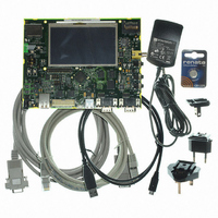
Description
KIT EVAL FOR AT91SAM9G45
Manufacturer
Atmel
Series
AT91SAM Smart ARMr
Type
MCUr
Datasheets
1.AT91SAM9G45-EKES.pdf
(56 pages)
2.AT91SAM9G45-EKES.pdf
(1218 pages)
3.AT91SAM9G45-EKES.pdf
(66 pages)
Specifications of AT91SAM9G45-EKES
Contents
Board
Processor To Be Evaluated
SAM9G45
Data Bus Width
32 bit
Interface Type
I2C, SPI, UART
Maximum Operating Temperature
+ 50 C
Minimum Operating Temperature
- 10 C
Operating Supply Voltage
1.8 V to 3.3 V
For Use With/related Products
AT91SAM9G45
Lead Free Status / RoHS Status
Lead free / RoHS Compliant
Other names
Q4626953


Figure 43-6. Audio Transfer (PCM L Front, PCM R Front) on Channel x
43.7.3.5
43.7.3.6
1060
Read access to
(Codec output)
AC97C_RHRx
(AC97C_SR)
RXRDYCx
AC97RX
AC97FS
AT91SAM9G45
Slot #
AC97 Input Frame
Configuring and Using Interrupts
TAG
0
The application can also wait for an interrupt notice in order to read data from AC97C_CxRHR.
The interrupt remains active until RXRDY is cleared by reading AC97C_CxSR.
The RXRDY flag in AC97C_CxSR is set automatically when data is received in the Channel x
shift register. Data is then shifted to AC97C_CxRHR.
If the previously received data has not been read by the application, the new data overwrites the
data already waiting in AC97C_CxRHR, therefore the OVRUN flag in AC97C_CxSR is raised.
The application can either poll the OVRUN flag in AC97C_CxSR or wait for an interrupt notice.
The interrupt remains active until the OVRUN flag in AC97C_CxSR is set.
The AC97 Controller can also be used in sound recording devices in association with an AC97
Codec. The AC97 Controller may also be exposed to heavy PCM transfers. The application can
use the PDC connected to channel A in order to reduce processor overhead and increase per-
formance especially under an operating system.
The PDC receive counter values must be equal to the number of PCM samples to be received,
each sample goes in one slot.
The AC97 Controller receives a thirteen slot frame on the AC-Link sent by the AC97 Codec. The
first slot (tag slot or slot 0) flags the validity of the entire frame and the validity of each slot;
whether a slot carries valid data or not. Slots 1 and 2 are used if the application requires status
informations from AC97 Codec. Slots [3:12] are used according to AC97 Controller Output
Channel Assignment Register (AC97C_ICA) content. The AC97 Controller will not receive any
data from any slot if AC97C_ICA is not assigned to a channel in input.
Instead of polling flags in AC97 Controller Global Status Register (AC97C_SR) and in AC97
Controller Channel x Status Register (AC97C_CxSR), the application can wait for an interrupt
notice. The following steps show how to configure and use interrupts correctly:
The interrupt handler must read both AC97 Controller Global Status Register (AC97C_SR) and
AC97 Controller Interrupt Mask Register (AC97C_IMR) and AND them to get the real interrupt
source. Furthermore, to get which event was activated, the interrupt handler has to read AC97
Controller Channel x Status Register (AC97C_CxSR), x being the channel whose event triggers
the interrupt.
STATUS
• Set the interruptible flag in AC97 Controller Channel x Mode Register (AC97C_CxMR).
• Set the interruptible event and channel event in AC97 Controller Interrupt Enable Register
ADDR
(AC97C_IER).
1
STATUS
DATA
2
LEFT
3
PCM
RIGHT
4
PCM
LINE 1
DAC
5
6
PCM
MIC
RSVED
7
RSVED
8
RSVED
9
LINE 2
ADC
10
6438F–ATARM–21-Jun-10
HSET
11
ADC
STATUS
12
IO
Related parts for AT91SAM9G45-EKES
Image
Part Number
Description
Manufacturer
Datasheet
Request
R

Part Number:
Description:
MCU ARM9 64K SRAM 144-LFBGA
Manufacturer:
Atmel
Datasheet:

Part Number:
Description:
IC ARM7 MCU FLASH 256K 100LQFP
Manufacturer:
Atmel
Datasheet:

Part Number:
Description:
IC ARM9 MPU 217-LFBGA
Manufacturer:
Atmel
Datasheet:
Part Number:
Description:
MCU ARM9 ULTRA LOW PWR 217-LFBGA
Manufacturer:
Atmel
Datasheet:

Part Number:
Description:
MCU ARM9 324-TFBGA
Manufacturer:
Atmel
Datasheet:
Part Number:
Description:
IC MCU ARM9 SAMPLING 217CBGA
Manufacturer:
Atmel
Datasheet:
Part Number:
Description:
IC ARM9 MCU 217-LFBGA
Manufacturer:
Atmel
Datasheet:

Part Number:
Description:
IC ARM9 MCU 208-PQFP
Manufacturer:
Atmel
Datasheet:
Part Number:
Description:
MCU ARM 512K HS FLASH 100-LQFP
Manufacturer:
Atmel
Datasheet:

Part Number:
Description:
MCU ARM 512K HS FLASH 100-TFBGA
Manufacturer:
Atmel
Datasheet:
Part Number:
Description:
IC ARM9 MCU 200 MHZ 324-TFBGA
Manufacturer:
Atmel
Datasheet:

Part Number:
Description:
IC ARM MCU 16BIT 128K 256BGA
Manufacturer:
Atmel
Datasheet:

Part Number:
Description:
IC ARM7 MCU 32BIT 128K 64LQFP
Manufacturer:
Atmel
Datasheet:

Part Number:
Description:
IC ARM7 MCU FLASH 256K 128-LQFP
Manufacturer:
Atmel
Datasheet:
Part Number:
Description:
IC ARM7 MCU FLASH 512K 128-LQFP
Manufacturer:
Atmel
Datasheet: