AT91SAM9G45-EKES Atmel, AT91SAM9G45-EKES Datasheet - Page 668
AT91SAM9G45-EKES
Manufacturer Part Number
AT91SAM9G45-EKES
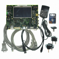
Description
KIT EVAL FOR AT91SAM9G45
Manufacturer
Atmel
Series
AT91SAM Smart ARMr
Type
MCUr
Datasheets
1.AT91SAM9G45-EKES.pdf
(56 pages)
2.AT91SAM9G45-EKES.pdf
(1218 pages)
3.AT91SAM9G45-EKES.pdf
(66 pages)
Specifications of AT91SAM9G45-EKES
Contents
Board
Processor To Be Evaluated
SAM9G45
Data Bus Width
32 bit
Interface Type
I2C, SPI, UART
Maximum Operating Temperature
+ 50 C
Minimum Operating Temperature
- 10 C
Operating Supply Voltage
1.8 V to 3.3 V
For Use With/related Products
AT91SAM9G45
Lead Free Status / RoHS Status
Lead free / RoHS Compliant
Other names
Q4626953


34.7.1.1
Figure 34-5. Divided Clock Block Diagram
Figure 34-6.
34.7.1.2
668
AT91SAM9G45
Clock Divider
Transmitter Clock Management
Divided Clock Generation
The Master Clock divider is determined by the 12-bit field DIV counter and comparator (so its
maximal value is 4095) in the Clock Mode Register SSC_CMR, allowing a Master Clock division
by up to 8190. The Divided Clock is provided to both the Receiver and Transmitter. When this
field is programmed to 0, the Clock Divider is not used and remains inactive.
When DIV is set to a value equal to or greater than 1, the Divided Clock has a frequency of Mas-
ter Clock divided by 2 times DIV. Each level of the Divided Clock has a duration of the Master
Clock multiplied by DIV. This ensures a 50% duty cycle for the Divided Clock regardless of
whether the DIV value is even or odd.
Table 34-4.
The transmitter clock is generated from the receiver clock or the divider clock or an external
clock scanned on the TK I/O pad. The transmitter clock is selected by the CKS field in
SSC_TCMR (Transmit Clock Mode Register). Transmit Clock can be inverted independently by
the CKI bits in SSC_TCMR.
The transmitter can also drive the TK I/O pad continuously or be limited to the actual data trans-
fer. The clock output is configured by the SSC_TCMR register. The Transmit Clock Inversion
(CKI) bits have no effect on the clock outputs. Programming the TCMR register to select TK pin
Maximum
MCK / 2
Divided Clock
Divided Clock
Master Clock
Master Clock
DIV = 3
DIV = 1
MCK
/ 2
Divided Clock Frequency = MCK/2
Divided Clock Frequency = MCK/6
Clock Divider
12-bit Counter
SSC_CMR
Minimum
MCK / 8190
Divided Clock
6438F–ATARM–21-Jun-10
Related parts for AT91SAM9G45-EKES
Image
Part Number
Description
Manufacturer
Datasheet
Request
R

Part Number:
Description:
MCU ARM9 64K SRAM 144-LFBGA
Manufacturer:
Atmel
Datasheet:

Part Number:
Description:
IC ARM7 MCU FLASH 256K 100LQFP
Manufacturer:
Atmel
Datasheet:

Part Number:
Description:
IC ARM9 MPU 217-LFBGA
Manufacturer:
Atmel
Datasheet:
Part Number:
Description:
MCU ARM9 ULTRA LOW PWR 217-LFBGA
Manufacturer:
Atmel
Datasheet:

Part Number:
Description:
MCU ARM9 324-TFBGA
Manufacturer:
Atmel
Datasheet:
Part Number:
Description:
IC MCU ARM9 SAMPLING 217CBGA
Manufacturer:
Atmel
Datasheet:
Part Number:
Description:
IC ARM9 MCU 217-LFBGA
Manufacturer:
Atmel
Datasheet:

Part Number:
Description:
IC ARM9 MCU 208-PQFP
Manufacturer:
Atmel
Datasheet:
Part Number:
Description:
MCU ARM 512K HS FLASH 100-LQFP
Manufacturer:
Atmel
Datasheet:

Part Number:
Description:
MCU ARM 512K HS FLASH 100-TFBGA
Manufacturer:
Atmel
Datasheet:
Part Number:
Description:
IC ARM9 MCU 200 MHZ 324-TFBGA
Manufacturer:
Atmel
Datasheet:

Part Number:
Description:
IC ARM MCU 16BIT 128K 256BGA
Manufacturer:
Atmel
Datasheet:

Part Number:
Description:
IC ARM7 MCU 32BIT 128K 64LQFP
Manufacturer:
Atmel
Datasheet:

Part Number:
Description:
IC ARM7 MCU FLASH 256K 128-LQFP
Manufacturer:
Atmel
Datasheet:
Part Number:
Description:
IC ARM7 MCU FLASH 512K 128-LQFP
Manufacturer:
Atmel
Datasheet: