AT91SAM9G45-EKES Atmel, AT91SAM9G45-EKES Datasheet - Page 991
AT91SAM9G45-EKES
Manufacturer Part Number
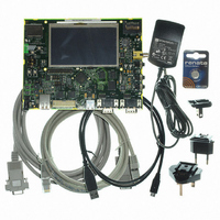
AT91SAM9G45-EKES
Description
KIT EVAL FOR AT91SAM9G45
Manufacturer
Atmel
Series
AT91SAM Smart ARMr
Type
MCUr
Datasheets
1.AT91SAM9G45-EKES.pdf
(56 pages)
2.AT91SAM9G45-EKES.pdf
(1218 pages)
3.AT91SAM9G45-EKES.pdf
(66 pages)
Specifications of AT91SAM9G45-EKES
Contents
Board
Processor To Be Evaluated
SAM9G45
Data Bus Width
32 bit
Interface Type
I2C, SPI, UART
Maximum Operating Temperature
+ 50 C
Minimum Operating Temperature
- 10 C
Operating Supply Voltage
1.8 V to 3.3 V
For Use With/related Products
AT91SAM9G45
Lead Free Status / RoHS Status
Lead free / RoHS Compliant
Other names
Q4626953


Figure 41-9. Multi-buffer DMAC Transfer with Source and Destination Address Auto-reloaded
6438F–ATARM–21-Jun-10
Source Layer
Address of
6. The DMAC transfer proceeds as follows:
Channel Enable in the Channel Status Register (DMAC_CHSR.ENABLE[n]) until it is
disabled, to detect when the transfer is complete. If the DMAC is not in Row 1, the next
step is performed.
a. If interrupts is un-masked (DMAC_EBCIMR.BTC[x] = ‘1’, where x is the channel
b. If the buffer complete interrupt is masked (DMAC_EBCIMR.BTC[x] = ‘1’, where x is
SADDR
number) hardware sets the buffer complete interrupt when the buffer transfer has
completed. It then stalls until the STALLED[n] bit of DMAC_CHSR register is
cleared by software, writing ‘1’ to DMAC_CHER.KEEPON[n] bit where n is the
channel number. If the next buffer is to be the last buffer in the DMAC transfer, then
the buffer complete ISR (interrupt service routine) should clear the automatic mode
bit in the DMAC_CTRLBx.AUTO bit. This put the DMAC into Row 1 as shown in
Table 41-2 on page
fer, then the reload bits should remain enabled to keep the DMAC in Row 4.
the channel number), then hardware does not stall until it detects a write to the buf-
fer complete interrupt enable register DMAC_EBCIER register but starts the next
buffer transfer immediately. In this case software must clear the automatic mode bit
in the DMAC_CTRLB to put the DMAC into ROW 1 of
before the last buffer of the DMAC transfer has completed. The transfer is similar to
that shown in
41-10 on page
Source Buffers
Figure 41-9 on page
992.
982. If the next buffer is not the last buffer in the DMAC trans-
Block2
Block1
Block0
BlockN
Destination Buffers
991. The DMAC transfer flow is shown in
DADDR
Destination Layer
Address of
Table 41-2 on page 982
AT91SAM9G45
Figure
991
Related parts for AT91SAM9G45-EKES
Image
Part Number
Description
Manufacturer
Datasheet
Request
R

Part Number:
Description:
MCU ARM9 64K SRAM 144-LFBGA
Manufacturer:
Atmel
Datasheet:

Part Number:
Description:
IC ARM7 MCU FLASH 256K 100LQFP
Manufacturer:
Atmel
Datasheet:

Part Number:
Description:
IC ARM9 MPU 217-LFBGA
Manufacturer:
Atmel
Datasheet:
Part Number:
Description:
MCU ARM9 ULTRA LOW PWR 217-LFBGA
Manufacturer:
Atmel
Datasheet:

Part Number:
Description:
MCU ARM9 324-TFBGA
Manufacturer:
Atmel
Datasheet:
Part Number:
Description:
IC MCU ARM9 SAMPLING 217CBGA
Manufacturer:
Atmel
Datasheet:
Part Number:
Description:
IC ARM9 MCU 217-LFBGA
Manufacturer:
Atmel
Datasheet:

Part Number:
Description:
IC ARM9 MCU 208-PQFP
Manufacturer:
Atmel
Datasheet:
Part Number:
Description:
MCU ARM 512K HS FLASH 100-LQFP
Manufacturer:
Atmel
Datasheet:

Part Number:
Description:
MCU ARM 512K HS FLASH 100-TFBGA
Manufacturer:
Atmel
Datasheet:
Part Number:
Description:
IC ARM9 MCU 200 MHZ 324-TFBGA
Manufacturer:
Atmel
Datasheet:

Part Number:
Description:
IC ARM MCU 16BIT 128K 256BGA
Manufacturer:
Atmel
Datasheet:

Part Number:
Description:
IC ARM7 MCU 32BIT 128K 64LQFP
Manufacturer:
Atmel
Datasheet:

Part Number:
Description:
IC ARM7 MCU FLASH 256K 128-LQFP
Manufacturer:
Atmel
Datasheet:
Part Number:
Description:
IC ARM7 MCU FLASH 512K 128-LQFP
Manufacturer:
Atmel
Datasheet: