AT91SAM9G45-EKES Atmel, AT91SAM9G45-EKES Datasheet - Page 359
AT91SAM9G45-EKES
Manufacturer Part Number
AT91SAM9G45-EKES
Description
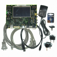
KIT EVAL FOR AT91SAM9G45
Manufacturer
Atmel
Series
AT91SAM Smart ARMr
Type
MCUr
Datasheets
1.AT91SAM9G45-EKES.pdf
(56 pages)
2.AT91SAM9G45-EKES.pdf
(1218 pages)
3.AT91SAM9G45-EKES.pdf
(66 pages)
Specifications of AT91SAM9G45-EKES
Contents
Board
Processor To Be Evaluated
SAM9G45
Data Bus Width
32 bit
Interface Type
I2C, SPI, UART
Maximum Operating Temperature
+ 50 C
Minimum Operating Temperature
- 10 C
Operating Supply Voltage
1.8 V to 3.3 V
For Use With/related Products
AT91SAM9G45
Lead Free Status / RoHS Status
Lead free / RoHS Compliant
Other names
Q4626953


Figure 27-4. Start Bit Detection
Figure 27-5. Character Reception
27.5.2.3
Figure 27-6. Receiver Ready
27.5.2.4
Figure 27-7. Receiver Overrun
27.5.2.5
6438F–ATARM–21-Jun-10
Receiver Ready
Receiver Overrun
Parity Error
Example: 8-bit, parity enabled 1 stop
Sampling
RXRDY
Sampling Clock
RXRDY
OVRE
DRXD
DRXD
DRXD
Baud Rate
DRXD
Clock
S
S
When a complete character is received, it is transferred to the DBGU_RHR and the RXRDY sta-
tus bit in DBGU_SR (Status Register) is set. The bit RXRDY is automatically cleared when the
receive holding register DBGU_RHR is read.
If DBGU_RHR has not been read by the software (or the Peripheral Data Controller) since the
last transfer, the RXRDY bit is still set and a new character is received, the OVRE status bit in
DBGU_SR is set. OVRE is cleared when the software writes the control register DBGU_CR with
the bit RSTSTA (Reset Status) at 1.
Each time a character is received, the receiver calculates the parity of the received data bits, in
accordance with the field PAR in DBGU_MR. It then compares the result with the received parity
period
0.5 bit
D0
D0
True Start Detection
D1
D1
period
D2
1 bit
D2
D3
D0
D3
D4
D4
D1
D5
D5
D6
D6
True Start
Detection
D2
D7
D7
P
P
D3
stop
S
S
D4
Read DBGU_RHR
D0
D0
D1
D1
D5
D2
D2
D3
D3
D6
D4
D4
D5
D5
D7
D6
D6
Parity Bit
D7
D7
AT91SAM9G45
P
P
stop
Stop Bit
D0
RSTSTA
359
Related parts for AT91SAM9G45-EKES
Image
Part Number
Description
Manufacturer
Datasheet
Request
R

Part Number:
Description:
MCU ARM9 64K SRAM 144-LFBGA
Manufacturer:
Atmel
Datasheet:

Part Number:
Description:
IC ARM7 MCU FLASH 256K 100LQFP
Manufacturer:
Atmel
Datasheet:

Part Number:
Description:
IC ARM9 MPU 217-LFBGA
Manufacturer:
Atmel
Datasheet:
Part Number:
Description:
MCU ARM9 ULTRA LOW PWR 217-LFBGA
Manufacturer:
Atmel
Datasheet:

Part Number:
Description:
MCU ARM9 324-TFBGA
Manufacturer:
Atmel
Datasheet:
Part Number:
Description:
IC MCU ARM9 SAMPLING 217CBGA
Manufacturer:
Atmel
Datasheet:
Part Number:
Description:
IC ARM9 MCU 217-LFBGA
Manufacturer:
Atmel
Datasheet:

Part Number:
Description:
IC ARM9 MCU 208-PQFP
Manufacturer:
Atmel
Datasheet:
Part Number:
Description:
MCU ARM 512K HS FLASH 100-LQFP
Manufacturer:
Atmel
Datasheet:

Part Number:
Description:
MCU ARM 512K HS FLASH 100-TFBGA
Manufacturer:
Atmel
Datasheet:
Part Number:
Description:
IC ARM9 MCU 200 MHZ 324-TFBGA
Manufacturer:
Atmel
Datasheet:

Part Number:
Description:
IC ARM MCU 16BIT 128K 256BGA
Manufacturer:
Atmel
Datasheet:

Part Number:
Description:
IC ARM7 MCU 32BIT 128K 64LQFP
Manufacturer:
Atmel
Datasheet:

Part Number:
Description:
IC ARM7 MCU FLASH 256K 128-LQFP
Manufacturer:
Atmel
Datasheet:
Part Number:
Description:
IC ARM7 MCU FLASH 512K 128-LQFP
Manufacturer:
Atmel
Datasheet: