AT91SAM9G45-EKES Atmel, AT91SAM9G45-EKES Datasheet - Page 597
AT91SAM9G45-EKES
Manufacturer Part Number
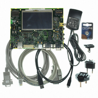
AT91SAM9G45-EKES
Description
KIT EVAL FOR AT91SAM9G45
Manufacturer
Atmel
Series
AT91SAM Smart ARMr
Type
MCUr
Datasheets
1.AT91SAM9G45-EKES.pdf
(56 pages)
2.AT91SAM9G45-EKES.pdf
(1218 pages)
3.AT91SAM9G45-EKES.pdf
(66 pages)
Specifications of AT91SAM9G45-EKES
Contents
Board
Processor To Be Evaluated
SAM9G45
Data Bus Width
32 bit
Interface Type
I2C, SPI, UART
Maximum Operating Temperature
+ 50 C
Minimum Operating Temperature
- 10 C
Operating Supply Voltage
1.8 V to 3.3 V
For Use With/related Products
AT91SAM9G45
Lead Free Status / RoHS Status
Lead free / RoHS Compliant
Other names
Q4626953


33.7.7.5
33.7.7.6
33.7.7.7
6438F–ATARM–21-Jun-10
Character Transmission
Character Reception
Receiver Timeout
The characters are sent by writing in the Transmit Holding Register (US_THR). The transmitter
reports two status bits in the Channel Status Register (US_CSR): TXRDY (Transmitter Ready),
which indicates that US_THR is empty and TXEMPTY, which indicates that all the characters
written in US_THR have been processed. When the current character processing is completed,
the last character written in US_THR is transferred into the Shift Register of the transmitter and
US_THR becomes empty, thus TXRDY rises.
Both TXRDY and TXEMPTY bits are low when the transmitter is disabled. Writing a character in
US_THR while TXRDY is low has no effect and the written character is lost.
If the USART is in SPI Slave Mode and if a character must be sent while the Transmit Holding
Register (US_THR) is empty, the UNRE (Underrun Error) bit is set. The TXD transmission line
stays at high level during all this time. The UNRE bit is cleared by writing the Control Register
(US_CR) with the RSTSTA (Reset Status) bit at 1.
In SPI Master Mode, the slave select line (NSS) is asserted at low level 1 Tbit before the trans-
mission of the MSB bit and released at high level 1 Tbit after the transmission of the LSB bit. So,
the slave select line (NSS) is always released between each character transmission and a mini-
mum delay of 3 Tbits always inserted. However, in order to address slave devices supporting the
CSAAT mode (Chip Select Active After Transfer), the slave select line (NSS) can be forced at
low level by writing the Control Register (US_CR) with the RTSEN bit at 1. The slave select line
(NSS) can be released at high level only by writing the Control Register (US_CR) with the RTS-
DIS bit at 1 (for example, when all data have been transferred to the slave device).
In SPI Slave Mode, the transmitter does not require a falling edge of the slave select line (NSS)
to initiate a character transmission but only a low level. However, this low level must be present
on the slave select line (NSS) at least 1 Tbit before the first serial clock cycle corresponding to
the MSB bit.
When a character reception is completed, it is transferred to the Receive Holding Register
(US_RHR) and the RXRDY bit in the Status Register (US_CSR) rises. If a character is com-
pleted while RXRDY is set, the OVRE (Overrun Error) bit is set. The last character is transferred
into US_RHR and overwrites the previous one. The OVRE bit is cleared by writing the Control
Register (US_CR) with the RSTSTA (Reset Status) bit at 1.
To ensure correct behavior of the receiver in SPI Slave Mode, the master device sending the
frame must ensure a minimum delay of 1 Tbit between each character transmission. The
receiver does not require a falling edge of the slave select line (NSS) to initiate a character
reception but only a low level. However, this low level must be present on the slave select line
(NSS) at least 1 Tbit before the first serial clock cycle corresponding to the MSB bit.
Because the receiver baudrate clock is active only during data transfers in SPI Mode, a receiver
timeout is impossible in this mode, whatever the Time-out value is (field TO) in the Time-out
Register (US_RTOR).
AT91SAM9G45
597
Related parts for AT91SAM9G45-EKES
Image
Part Number
Description
Manufacturer
Datasheet
Request
R

Part Number:
Description:
MCU ARM9 64K SRAM 144-LFBGA
Manufacturer:
Atmel
Datasheet:

Part Number:
Description:
IC ARM7 MCU FLASH 256K 100LQFP
Manufacturer:
Atmel
Datasheet:

Part Number:
Description:
IC ARM9 MPU 217-LFBGA
Manufacturer:
Atmel
Datasheet:
Part Number:
Description:
MCU ARM9 ULTRA LOW PWR 217-LFBGA
Manufacturer:
Atmel
Datasheet:

Part Number:
Description:
MCU ARM9 324-TFBGA
Manufacturer:
Atmel
Datasheet:
Part Number:
Description:
IC MCU ARM9 SAMPLING 217CBGA
Manufacturer:
Atmel
Datasheet:
Part Number:
Description:
IC ARM9 MCU 217-LFBGA
Manufacturer:
Atmel
Datasheet:

Part Number:
Description:
IC ARM9 MCU 208-PQFP
Manufacturer:
Atmel
Datasheet:
Part Number:
Description:
MCU ARM 512K HS FLASH 100-LQFP
Manufacturer:
Atmel
Datasheet:

Part Number:
Description:
MCU ARM 512K HS FLASH 100-TFBGA
Manufacturer:
Atmel
Datasheet:
Part Number:
Description:
IC ARM9 MCU 200 MHZ 324-TFBGA
Manufacturer:
Atmel
Datasheet:

Part Number:
Description:
IC ARM MCU 16BIT 128K 256BGA
Manufacturer:
Atmel
Datasheet:

Part Number:
Description:
IC ARM7 MCU 32BIT 128K 64LQFP
Manufacturer:
Atmel
Datasheet:

Part Number:
Description:
IC ARM7 MCU FLASH 256K 128-LQFP
Manufacturer:
Atmel
Datasheet:
Part Number:
Description:
IC ARM7 MCU FLASH 512K 128-LQFP
Manufacturer:
Atmel
Datasheet: