AT91SAM9G45-EKES Atmel, AT91SAM9G45-EKES Datasheet - Page 599
AT91SAM9G45-EKES
Manufacturer Part Number
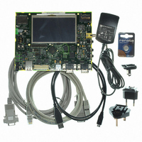
AT91SAM9G45-EKES
Description
KIT EVAL FOR AT91SAM9G45
Manufacturer
Atmel
Series
AT91SAM Smart ARMr
Type
MCUr
Datasheets
1.AT91SAM9G45-EKES.pdf
(56 pages)
2.AT91SAM9G45-EKES.pdf
(1218 pages)
3.AT91SAM9G45-EKES.pdf
(66 pages)
Specifications of AT91SAM9G45-EKES
Contents
Board
Processor To Be Evaluated
SAM9G45
Data Bus Width
32 bit
Interface Type
I2C, SPI, UART
Maximum Operating Temperature
+ 50 C
Minimum Operating Temperature
- 10 C
Operating Supply Voltage
1.8 V to 3.3 V
For Use With/related Products
AT91SAM9G45
Lead Free Status / RoHS Status
Lead free / RoHS Compliant
Other names
Q4626953


33.7.8.5
Figure 33-40. Header Transmission
6438F–ATARM–21-Jun-10
Write RSTSTA=1
in US_CSR
in US_CSR
Baud Rate
US_LINIR
US_LINIR
in US_CR
TXRDY
LINBK
LINID
Clock
Write
TXD
Header Transmission (Master Node Configuration)
ID
All the LIN Frames start with a header which is sent by the master node and consists of a Synch
Break Field, Synch Field and Identifier Field.
So in Master node configuration, the frame handling starts with the sending of the header.
The header is transmitted as soon as the identifier is written in the LIN Identifier register
(US_LINIR). At this moment the flag TXRDY falls.
The Break Field, the Synch Field and the Identifier Field are sent automatically one after the
other.
The Break Field consists of 13 dominant bits and 1 recessive bit, the Synch Field is the charac-
ter 0x55 and the Identifier corresponds to the character written in the LIN Identifier Register
(US_LINIR). The Identifier parity bits can be automatically computed and sent (see
33.7.8.8).
The flag TXRDY rises when the identifier character is transferred into the Shift Register of the
transmitter.As soon as the Synch Break Field is transmitted, the flag LINBK in the Channel Sta-
tus register (US_CSR) is set to “1”. Likewise, as soon as the Identifier Field is sent, the flag
LINID in the Channel Status register (US_CSR) is set to “1”. These flags are reset by writing the
bit RSTSTA at “1” in the Control register (US_CR).
13 dominant bits (at 0)
Break Field
1 recessive bit
Delimiter
Break
(at 1)
Start
Bit
1
0
Synch Byte = 0x55
1
0
1
0
1
0
Stop
Bit
Start
Bit
ID0
ID1
AT91SAM9G45
ID2
ID3
ID4
ID5
ID6
ID7
Stop
Bit
Section
599
Related parts for AT91SAM9G45-EKES
Image
Part Number
Description
Manufacturer
Datasheet
Request
R

Part Number:
Description:
MCU ARM9 64K SRAM 144-LFBGA
Manufacturer:
Atmel
Datasheet:

Part Number:
Description:
IC ARM7 MCU FLASH 256K 100LQFP
Manufacturer:
Atmel
Datasheet:

Part Number:
Description:
IC ARM9 MPU 217-LFBGA
Manufacturer:
Atmel
Datasheet:
Part Number:
Description:
MCU ARM9 ULTRA LOW PWR 217-LFBGA
Manufacturer:
Atmel
Datasheet:

Part Number:
Description:
MCU ARM9 324-TFBGA
Manufacturer:
Atmel
Datasheet:
Part Number:
Description:
IC MCU ARM9 SAMPLING 217CBGA
Manufacturer:
Atmel
Datasheet:
Part Number:
Description:
IC ARM9 MCU 217-LFBGA
Manufacturer:
Atmel
Datasheet:

Part Number:
Description:
IC ARM9 MCU 208-PQFP
Manufacturer:
Atmel
Datasheet:
Part Number:
Description:
MCU ARM 512K HS FLASH 100-LQFP
Manufacturer:
Atmel
Datasheet:

Part Number:
Description:
MCU ARM 512K HS FLASH 100-TFBGA
Manufacturer:
Atmel
Datasheet:
Part Number:
Description:
IC ARM9 MCU 200 MHZ 324-TFBGA
Manufacturer:
Atmel
Datasheet:

Part Number:
Description:
IC ARM MCU 16BIT 128K 256BGA
Manufacturer:
Atmel
Datasheet:

Part Number:
Description:
IC ARM7 MCU 32BIT 128K 64LQFP
Manufacturer:
Atmel
Datasheet:

Part Number:
Description:
IC ARM7 MCU FLASH 256K 128-LQFP
Manufacturer:
Atmel
Datasheet:
Part Number:
Description:
IC ARM7 MCU FLASH 512K 128-LQFP
Manufacturer:
Atmel
Datasheet: