AT91SAM9G45-EKES Atmel, AT91SAM9G45-EKES Datasheet - Page 952
AT91SAM9G45-EKES
Manufacturer Part Number
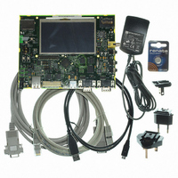
AT91SAM9G45-EKES
Description
KIT EVAL FOR AT91SAM9G45
Manufacturer
Atmel
Series
AT91SAM Smart ARMr
Type
MCUr
Datasheets
1.AT91SAM9G45-EKES.pdf
(56 pages)
2.AT91SAM9G45-EKES.pdf
(1218 pages)
3.AT91SAM9G45-EKES.pdf
(66 pages)
Specifications of AT91SAM9G45-EKES
Contents
Board
Processor To Be Evaluated
SAM9G45
Data Bus Width
32 bit
Interface Type
I2C, SPI, UART
Maximum Operating Temperature
+ 50 C
Minimum Operating Temperature
- 10 C
Operating Supply Voltage
1.8 V to 3.3 V
For Use With/related Products
AT91SAM9G45
Lead Free Status / RoHS Status
Lead free / RoHS Compliant
Other names
Q4626953


40.10.4
6438F–ATARM–21-Jun-10
Manual Mode
The Trigger Counter is cleared when TSAMOD is written to define the Interleaved Mode, then it
simply rolls over.
The TSADCC features a manual mode allowing to control the state (open/close) of the four
switches.
Writing TSAMOD to “Manual Mode” automatically enables the ADC pins as analog inputs.The
switches positions are controlled through the
this mode, the “Sample and Hold Time” used is the one defined for the Touchscreen mode
(TSSHTIM).
To perform a measurement, the following sequence must be followed
• For Trigger Counter at 5:
1. Close the switches on the inputs Y
2. Convert Channel Y
3. If Channel 4 to Channel 7 are enabled, convert Channels and store result in the corre-
4. Set Trigger Counter to 6.
• For Trigger Counter at 6:
1. Close the switches on the inputs Y
2. Convert Channel Y
3. If Channel 4 to Channel 7 are enabled, convert Channels and store result in the corre-
4. Set Trigger Counter to 7.
• For Trigger Counter at 7:
1. Close the switches on the inputs Y
2. Convert Channel X
3. If Channel 4 to Channel 7 are enabled, convert Channels and store result in the corre-
4. Set Trigger Counter to 8.
• For Trigger Counter between 8 and (2
1. Increment Trigger Counter.
2. If Trigger Counter equals (2
3. If Channel 4 to Channel 7 are enabled, convert Channels and store result in the corre-
1. Select the switch (switches) to close.
2. If SLEEP is set, wake up the ADC cell and wait for the Startup Time.
TSADCC_XPDR in TSADCC_LCDR if PDCEN is enabled).
sponding TSADCC_CDRx and TSADCC_LCDR.
result in TSADCC_CDR2 (and also in TSADCC_LCDR if PDCEN is enabled).
sponding TSADCC_CDRx and TSADCC_LCDR.
result in TSADCC_CDR3 (and also in TSADCC_LCDR if PDCEN is enabled).
sponding TSADCC_CDRx and TSADCC_LCDR.
sponding TSADCC_CDRx and TSADCC_LCDR.
P
P
M
, subtract TSADCC_CDR3 from the result and store the subtraction
, subtract TSADCC_CDR3 from the result and store the subtraction
and store the result in TSADCC_CDR3 (and store content of
TSFREQ+1
P
P
P
TSFREQ+1
), then set Trigger Counter to 0.
and Y
and Y
and Y
“TSADCC Manual Switch Command
M
M
M
):
during the Sample and Hold Time.
during the Sample and Hold Time.
during the Sample and Hold Time
AT91SAM9G45
Register”. In
952
Related parts for AT91SAM9G45-EKES
Image
Part Number
Description
Manufacturer
Datasheet
Request
R

Part Number:
Description:
MCU ARM9 64K SRAM 144-LFBGA
Manufacturer:
Atmel
Datasheet:

Part Number:
Description:
IC ARM7 MCU FLASH 256K 100LQFP
Manufacturer:
Atmel
Datasheet:

Part Number:
Description:
IC ARM9 MPU 217-LFBGA
Manufacturer:
Atmel
Datasheet:
Part Number:
Description:
MCU ARM9 ULTRA LOW PWR 217-LFBGA
Manufacturer:
Atmel
Datasheet:

Part Number:
Description:
MCU ARM9 324-TFBGA
Manufacturer:
Atmel
Datasheet:
Part Number:
Description:
IC MCU ARM9 SAMPLING 217CBGA
Manufacturer:
Atmel
Datasheet:
Part Number:
Description:
IC ARM9 MCU 217-LFBGA
Manufacturer:
Atmel
Datasheet:

Part Number:
Description:
IC ARM9 MCU 208-PQFP
Manufacturer:
Atmel
Datasheet:
Part Number:
Description:
MCU ARM 512K HS FLASH 100-LQFP
Manufacturer:
Atmel
Datasheet:

Part Number:
Description:
MCU ARM 512K HS FLASH 100-TFBGA
Manufacturer:
Atmel
Datasheet:
Part Number:
Description:
IC ARM9 MCU 200 MHZ 324-TFBGA
Manufacturer:
Atmel
Datasheet:

Part Number:
Description:
IC ARM MCU 16BIT 128K 256BGA
Manufacturer:
Atmel
Datasheet:

Part Number:
Description:
IC ARM7 MCU 32BIT 128K 64LQFP
Manufacturer:
Atmel
Datasheet:

Part Number:
Description:
IC ARM7 MCU FLASH 256K 128-LQFP
Manufacturer:
Atmel
Datasheet:
Part Number:
Description:
IC ARM7 MCU FLASH 512K 128-LQFP
Manufacturer:
Atmel
Datasheet: