AT91SAM9G45-EKES Atmel, AT91SAM9G45-EKES Datasheet - Page 455
AT91SAM9G45-EKES
Manufacturer Part Number
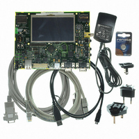
AT91SAM9G45-EKES
Description
KIT EVAL FOR AT91SAM9G45
Manufacturer
Atmel
Series
AT91SAM Smart ARMr
Type
MCUr
Datasheets
1.AT91SAM9G45-EKES.pdf
(56 pages)
2.AT91SAM9G45-EKES.pdf
(1218 pages)
3.AT91SAM9G45-EKES.pdf
(66 pages)
Specifications of AT91SAM9G45-EKES
Contents
Board
Processor To Be Evaluated
SAM9G45
Data Bus Width
32 bit
Interface Type
I2C, SPI, UART
Maximum Operating Temperature
+ 50 C
Minimum Operating Temperature
- 10 C
Operating Supply Voltage
1.8 V to 3.3 V
For Use With/related Products
AT91SAM9G45
Lead Free Status / RoHS Status
Lead free / RoHS Compliant
Other names
Q4626953


30.3
30.3.1
30.3.2
30.3.3
30.3.4
6438F–ATARM–21-Jun-10
Product Dependencies
Pin Multiplexing
External Interrupt Lines
Power Management
Interrupt Generation
Each pin is configurable, according to product definition as either a general-purpose I/O line
only, or as an I/O line multiplexed with one or two peripheral I/Os. As the multiplexing is hard-
ware-defined and thus product-dependent, the hardware designer and programmer must
carefully determine the configuration of the PIO controllers required by their application. When
an I/O line is general-purpose only, i.e. not multiplexed with any peripheral I/O, programming of
the PIO Controller regarding the assignment to a peripheral has no effect and only the PIO Con-
troller can control how the pin is driven by the product.
The interrupt signals FIQ and IRQ0 to IRQn are most generally multiplexed through the PIO
Controllers. However, it is not necessary to assign the I/O line to the interrupt function as the
PIO Controller has no effect on inputs and the interrupt lines (FIQ or IRQs) are used only as
inputs.
The Power Management Controller controls the PIO Controller clock in order to save power.
Writing any of the registers of the user interface does not require the PIO Controller clock to be
enabled. This means that the configuration of the I/O lines does not require the PIO Controller
clock to be enabled.
However, when the clock is disabled, not all of the features of the PIO Controller are available.
Note that the Input Change Interrupt and the read of the pin level require the clock to be
validated.
After a hardware reset, the PIO clock is disabled by default.
The user must configure the Power Management Controller before any access to the input line
information.
For interrupt handling, the PIO Controllers are considered as user peripherals. This means that
the PIO Controller interrupt lines are connected among the interrupt sources 2 to 31. Refer to the
PIO Controller peripheral identifier in the product description to identify the interrupt sources
dedicated to the PIO Controllers.
The PIO Controller interrupt can be generated only if the PIO Controller clock is enabled.
AT91SAM9G45
455
Related parts for AT91SAM9G45-EKES
Image
Part Number
Description
Manufacturer
Datasheet
Request
R

Part Number:
Description:
MCU ARM9 64K SRAM 144-LFBGA
Manufacturer:
Atmel
Datasheet:

Part Number:
Description:
IC ARM7 MCU FLASH 256K 100LQFP
Manufacturer:
Atmel
Datasheet:

Part Number:
Description:
IC ARM9 MPU 217-LFBGA
Manufacturer:
Atmel
Datasheet:
Part Number:
Description:
MCU ARM9 ULTRA LOW PWR 217-LFBGA
Manufacturer:
Atmel
Datasheet:

Part Number:
Description:
MCU ARM9 324-TFBGA
Manufacturer:
Atmel
Datasheet:
Part Number:
Description:
IC MCU ARM9 SAMPLING 217CBGA
Manufacturer:
Atmel
Datasheet:
Part Number:
Description:
IC ARM9 MCU 217-LFBGA
Manufacturer:
Atmel
Datasheet:

Part Number:
Description:
IC ARM9 MCU 208-PQFP
Manufacturer:
Atmel
Datasheet:
Part Number:
Description:
MCU ARM 512K HS FLASH 100-LQFP
Manufacturer:
Atmel
Datasheet:

Part Number:
Description:
MCU ARM 512K HS FLASH 100-TFBGA
Manufacturer:
Atmel
Datasheet:
Part Number:
Description:
IC ARM9 MCU 200 MHZ 324-TFBGA
Manufacturer:
Atmel
Datasheet:

Part Number:
Description:
IC ARM MCU 16BIT 128K 256BGA
Manufacturer:
Atmel
Datasheet:

Part Number:
Description:
IC ARM7 MCU 32BIT 128K 64LQFP
Manufacturer:
Atmel
Datasheet:

Part Number:
Description:
IC ARM7 MCU FLASH 256K 128-LQFP
Manufacturer:
Atmel
Datasheet:
Part Number:
Description:
IC ARM7 MCU FLASH 512K 128-LQFP
Manufacturer:
Atmel
Datasheet: