AT91SAM9G45-EKES Atmel, AT91SAM9G45-EKES Datasheet - Page 785
AT91SAM9G45-EKES
Manufacturer Part Number
AT91SAM9G45-EKES
Description
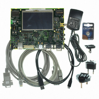
KIT EVAL FOR AT91SAM9G45
Manufacturer
Atmel
Series
AT91SAM Smart ARMr
Type
MCUr
Datasheets
1.AT91SAM9G45-EKES.pdf
(56 pages)
2.AT91SAM9G45-EKES.pdf
(1218 pages)
3.AT91SAM9G45-EKES.pdf
(66 pages)
Specifications of AT91SAM9G45-EKES
Contents
Board
Processor To Be Evaluated
SAM9G45
Data Bus Width
32 bit
Interface Type
I2C, SPI, UART
Maximum Operating Temperature
+ 50 C
Minimum Operating Temperature
- 10 C
Operating Supply Voltage
1.8 V to 3.3 V
For Use With/related Products
AT91SAM9G45
Lead Free Status / RoHS Status
Lead free / RoHS Compliant
Other names
Q4626953


36.9.1
36.9.2
36.10 CE-ATA Operation
36.10.1
6438F–ATARM–21-Jun-10
SDIO Data Transfer Type
SDIO Interrupts
Executing an ATA Polling Command
The SD/SDIO Card Register (HSMCI_SDCR) allows selection of the Card Slot and the data bus
width.
The SD/SDIO Card bus allows dynamic configuration of the number of data lines. After power
up, by default, the SD/SDIO Card uses only DAT0 for data transfer. After initialization, the host
can change the bus width (number of active data lines).
SDIO cards may transfer data in either a multi-byte (1 to 512 bytes) or an optional block format
(1 to 511 blocks), while the SD memory cards are fixed in the block transfer mode. The TRTYP
field in the HSMCI Command Register (HSMCI_CMDR) allows to choose between SDIO Byte or
SDIO Block transfer.
The number of bytes/blocks to transfer is set through the BCNT field in the HSMCI Block Regis-
ter (HSMCI_BLKR). In SDIO Block mode, the field BLKLEN must be set to the data block size
while this field is not used in SDIO Byte mode.
An SDIO Card can have multiple I/O or combined I/O and memory (called Combo Card). Within
a multi-function SDIO or a Combo card, there are multiple devices (I/O and memory) that share
access to the SD bus. In order to allow the sharing of access to the host among multiple devices,
SDIO and combo cards can implement the optional concept of suspend/resume (Refer to the
SDIO Specification for more details). To send a suspend or a resume command, the host must
set the SDIO Special Command field (IOSPCMD) in the HSMCI Command Register.
Each function within an SDIO or Combo card may implement interrupts (Refer to the SDIO
Specification for more details). In order to allow the SDIO card to interrupt the host, an interrupt
function is added to a pin on the DAT[1] line to signal the card’s interrupt to the host. An SDIO
interrupt on each slot can be enabled through the HSMCI Interrupt Enable Register. The SDIO
interrupt is sampled regardless of the currently selected slot.
CE-ATA maps the streamlined ATA command set onto the MMC interface. The ATA task file is
mapped onto MMC register space.
CE-ATA utilizes five MMC commands:
CE-ATA utilizes the same MMC command sequences for initialization as traditional MMC
devices.
• GO_IDLE_STATE (CMD0): used for hard reset.
• STOP_TRANSMISSION (CMD12): causes the ATA command currently executing to be
• FAST_IO (CMD39): Used for single register access to the ATA taskfile registers, 8 bit access
• RW_MULTIPLE_REGISTERS (CMD60): used to issue an ATA command or to access the
• RW_MULTIPLE_BLOCK (CMD61): used to transfer data for an ATA command.
1. Issue READ_DMA_EXT with RW_MULTIPLE_REGISTER (CMD60) for 8kB of DATA.
2. Read the ATA status register until DRQ is set.
aborted.
only.
control/status registers.
AT91SAM9G45
785
Related parts for AT91SAM9G45-EKES
Image
Part Number
Description
Manufacturer
Datasheet
Request
R

Part Number:
Description:
MCU ARM9 64K SRAM 144-LFBGA
Manufacturer:
Atmel
Datasheet:

Part Number:
Description:
IC ARM7 MCU FLASH 256K 100LQFP
Manufacturer:
Atmel
Datasheet:

Part Number:
Description:
IC ARM9 MPU 217-LFBGA
Manufacturer:
Atmel
Datasheet:
Part Number:
Description:
MCU ARM9 ULTRA LOW PWR 217-LFBGA
Manufacturer:
Atmel
Datasheet:

Part Number:
Description:
MCU ARM9 324-TFBGA
Manufacturer:
Atmel
Datasheet:
Part Number:
Description:
IC MCU ARM9 SAMPLING 217CBGA
Manufacturer:
Atmel
Datasheet:
Part Number:
Description:
IC ARM9 MCU 217-LFBGA
Manufacturer:
Atmel
Datasheet:

Part Number:
Description:
IC ARM9 MCU 208-PQFP
Manufacturer:
Atmel
Datasheet:
Part Number:
Description:
MCU ARM 512K HS FLASH 100-LQFP
Manufacturer:
Atmel
Datasheet:

Part Number:
Description:
MCU ARM 512K HS FLASH 100-TFBGA
Manufacturer:
Atmel
Datasheet:
Part Number:
Description:
IC ARM9 MCU 200 MHZ 324-TFBGA
Manufacturer:
Atmel
Datasheet:

Part Number:
Description:
IC ARM MCU 16BIT 128K 256BGA
Manufacturer:
Atmel
Datasheet:

Part Number:
Description:
IC ARM7 MCU 32BIT 128K 64LQFP
Manufacturer:
Atmel
Datasheet:

Part Number:
Description:
IC ARM7 MCU FLASH 256K 128-LQFP
Manufacturer:
Atmel
Datasheet:
Part Number:
Description:
IC ARM7 MCU FLASH 512K 128-LQFP
Manufacturer:
Atmel
Datasheet: