AT91SAM9G45-EKES Atmel, AT91SAM9G45-EKES Datasheet - Page 215
AT91SAM9G45-EKES
Manufacturer Part Number
AT91SAM9G45-EKES
Description
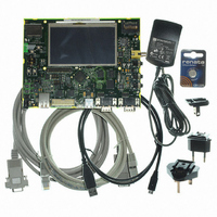
KIT EVAL FOR AT91SAM9G45
Manufacturer
Atmel
Series
AT91SAM Smart ARMr
Type
MCUr
Datasheets
1.AT91SAM9G45-EKES.pdf
(56 pages)
2.AT91SAM9G45-EKES.pdf
(1218 pages)
3.AT91SAM9G45-EKES.pdf
(66 pages)
Specifications of AT91SAM9G45-EKES
Contents
Board
Processor To Be Evaluated
SAM9G45
Data Bus Width
32 bit
Interface Type
I2C, SPI, UART
Maximum Operating Temperature
+ 50 C
Minimum Operating Temperature
- 10 C
Operating Supply Voltage
1.8 V to 3.3 V
For Use With/related Products
AT91SAM9G45
Lead Free Status / RoHS Status
Lead free / RoHS Compliant
Other names
Q4626953


21.12 Slow Clock Mode
21.12.1
Figure 21-31. Read/write Cycles in Slow Clock Mode
6438F–ATARM–21-Jun-10
NBS0, NBS1,
NBS2, NBS3,
A0,A1
Slow Clock Mode Waveforms
A[25:2]
NWE
MCK
NCS
SLOW CLOCK MODE WRITE
The SMC is able to automatically apply a set of “slow clock mode” read/write waveforms when
an internal signal driven by the Power Management Controller is asserted because MCK has
been turned to a very slow clock rate (typically 32kHz clock rate). In this mode, the user-pro-
grammed waveforms are ignored and the slow clock mode waveforms are applied. This mode is
provided so as to avoid reprogramming the User Interface with appropriate waveforms at very
slow clock rate. When activated, the slow mode is active on all chip selects.
Figure 21-31
chip selects.
1
Table 21-5.
Read Parameters
NRD_SETUP
NRD_PULSE
NCS_RD_SETUP
NCS_RD_PULSE
NRD_CYCLE
NWE_CYCLE = 3
1
Table 21-5
illustrates the read and write operations in slow clock mode. They are valid on all
Read and Write Timing Parameters in Slow Clock Mode
1
Duration (cycles)
indicates the value of read and write parameters in slow clock mode.
0
1
1
2
2
Write Parameters
NWE_SETUP
NWE_PULSE
NCS_WR_SETUP
NCS_WR_PULSE
NWE_CYCLE
NBS0, NBS1,
NBS2, NBS3,
A0,A1
A[25:2]
MCK
NRD
NCS
SLOW CLOCK MODE READ
NRD_CYCLE = 2
1
AT91SAM9G45
Duration (cycles)
1
1
1
0
3
3
215
Related parts for AT91SAM9G45-EKES
Image
Part Number
Description
Manufacturer
Datasheet
Request
R

Part Number:
Description:
MCU ARM9 64K SRAM 144-LFBGA
Manufacturer:
Atmel
Datasheet:

Part Number:
Description:
IC ARM7 MCU FLASH 256K 100LQFP
Manufacturer:
Atmel
Datasheet:

Part Number:
Description:
IC ARM9 MPU 217-LFBGA
Manufacturer:
Atmel
Datasheet:
Part Number:
Description:
MCU ARM9 ULTRA LOW PWR 217-LFBGA
Manufacturer:
Atmel
Datasheet:

Part Number:
Description:
MCU ARM9 324-TFBGA
Manufacturer:
Atmel
Datasheet:
Part Number:
Description:
IC MCU ARM9 SAMPLING 217CBGA
Manufacturer:
Atmel
Datasheet:
Part Number:
Description:
IC ARM9 MCU 217-LFBGA
Manufacturer:
Atmel
Datasheet:

Part Number:
Description:
IC ARM9 MCU 208-PQFP
Manufacturer:
Atmel
Datasheet:
Part Number:
Description:
MCU ARM 512K HS FLASH 100-LQFP
Manufacturer:
Atmel
Datasheet:

Part Number:
Description:
MCU ARM 512K HS FLASH 100-TFBGA
Manufacturer:
Atmel
Datasheet:
Part Number:
Description:
IC ARM9 MCU 200 MHZ 324-TFBGA
Manufacturer:
Atmel
Datasheet:

Part Number:
Description:
IC ARM MCU 16BIT 128K 256BGA
Manufacturer:
Atmel
Datasheet:

Part Number:
Description:
IC ARM7 MCU 32BIT 128K 64LQFP
Manufacturer:
Atmel
Datasheet:

Part Number:
Description:
IC ARM7 MCU FLASH 256K 128-LQFP
Manufacturer:
Atmel
Datasheet:
Part Number:
Description:
IC ARM7 MCU FLASH 512K 128-LQFP
Manufacturer:
Atmel
Datasheet: