XPSAF5130P SQUARE D, XPSAF5130P Datasheet - Page 10
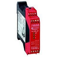
XPSAF5130P
Manufacturer Part Number
XPSAF5130P
Description
SAFETY RELAY 300V 2.5A PREVENTA
Manufacturer
SQUARE D
Datasheet
1.XPSMCCPC.pdf
(274 pages)
Specifications of XPSAF5130P
Contact Current Max
30mA
Contact Voltage Dc Nom
24V
Contact Configuration
3NO
Relay Mounting
DIN Rail
External Height
66mm
External Width
114mm
External Depth
22.5mm
Rohs Compliant
Yes


Description (continued)
Process status LEDs
2
1
2
1 Internal Ethernet LED
2 External Ethernet LEDs
Modbus® serial (RTU)
LEDs
PROFIBUS DP LEDs
PWR
PG
ERR
FAU
RUN
FOR
OSL
BL
1 5 9 13 17 21
2 6 10 14 18 22
3 7 11 15 19 23
4 8
12 16 20 24
T1 T5
T2 T6
T3 T7
T4 T8
1…24
T1…T8
PWR
PG
ERR
FAU
RUN
FOR
OSL
BL
LK/ACT
external
LK/ACT
internal
COM
RDY
RUN
ERR
Safety automation system solutions
Preventa™ safety PLCs
Compact, XPSMF40
LED details
Process status LEDs on safety PLCs XPSMF40pp
LED
Ethernet LEDs on safety PLCs XPSMF40pp
Modbus® serial (RTU) LEDs on safety PLCs XPSMF4020/MF4022
PROFIBUS DP LEDs on safety PLCs XPSMF4040/MF4042
Color
Green
Green
Green
Yellow
Red
Orange On
Green
Green
Orange Flashing
Orange Flashing
Green
Green
Yellow
Green
Green
Red
Status
On
On
On
Off
On
Flashing
Off
On
Off
Flashing
Off
On
Flashing
Off
On
Flashing
Off
Off
On
Flashing
Off
On
Flashing
Off
On
Off
On
Off
On
Off
On
Flashing
Meaning
Channels configured as inputs: input signal being received.
Channels configured as outputs: output signal being sent.
Line control outputs active.
c 24 V voltage present.
No voltage.
The CPU is being loaded with a new configuration.
The FLASH ROM is being loaded with a new operating system.
No loading of configuration or operating system.
Software error or hardware anomaly detected by the CPU.
The monitoring program (Watchdog) has triggered the STOP
state of the process because the programmed cycle time has
been exceeded.
The CPU has stopped the execution of the user application,
ended all hardware and software tests and all outputs have
been reset.
The process can only be started again from the PC.
No errors detected.
Error display for line control.
The user application has caused an error.
The system configuration is defective.
The loading of a new operating system was defective and the
operating system is corrupt.
An error has occurred while writing to FLASH ROM memory
(during updating of the operating system).
One or more I/O errors have occurred.
None of the above errors have occurred.
Normal service mode, loaded program running, the PLC
receives I/O messages, communication and hardware/software
tests carried out.
The CPU is in STOP and is not executing any user application.
All the outputs are reset to a safe, de-energized state.
The CPU is in “ERROR” state (see ERR).
The CPU is in RUN mode and force is active.
The system is not processing (STOP), but force is prepared and
is activated if the triple processor is started.
Force mode not activated.
Emergency loading of the operating system is active.
COM in INIT_Fail state.
No connection/link established.
Connection established/link established.
External data exchange (speed 10…100 Mbps).
No connection/link established.
Connection established/link established.
Internal data exchange (speed 10…100 Mbps).
No bus network signals being received or transmitted.
Bus network signals being received or transmitted.
Transmission power not available.
Equipment on.
Equipment not connected or not operational.
Equipment operational.
Transmission power not available or the slave is exchanging
data.
Connection to other equipment is established but no data
exchange is possible.
Bus disconnected or bus Master not available.
A configuration error has occurred and no data exchange is
possible.
2/9
10
10
1
1
2
2
3
3
4
4
5
5
6
6
7
7
8
8
9
9
Related parts for XPSAF5130P
Image
Part Number
Description
Manufacturer
Datasheet
Request
R


Part Number:
Description:
Pushbutton, Non-Illum'd Red "STOP", Momentary, 1NO-1NC, Square 30mm, 10A, 600V
Manufacturer:
SQUARE D
Datasheet:

Part Number:
Description:
KITS,TWIDO? PROGRAMMABLE CONTROLLERS,KITS,TWIDOPACK STARTER KIT - ADVANCED LEVEL,PROGRAMMABLE CONTROLLERS,TWIDO? PROGRAMMABLE CONTROLLERS ,SQUARE D
Manufacturer:
SQUARE D

Part Number:
Description:
LAMPS,INDICATOR,STACKABLE,LAMPS, STACKABLE INDICATOR,VISUAL INDICATING SIGNALS,XVB SERIES INDICATING BANKS ,SQUARE D
Manufacturer:
SQUARE D
Part Number:
Description:
LAMPS,INDICATOR,STACKABLE,LAMPS, STACKABLE INDICATOR,VISUAL INDICATING SIGNALS,XVB SERIES INDICATING BANKS ,SQUARE D
Manufacturer:
SQUARE D
Datasheet:
Part Number:
Description:
I/O EXTENDER MODULE 4 D IN & 2 D OUTPUT
Manufacturer:
SQUARE D
Datasheet:
Part Number:
Description:
CB ACCESSORY, UNDERVOLTAGE TRIP 48V DC
Manufacturer:
SQUARE D
Datasheet: