XPSAF5130P SQUARE D, XPSAF5130P Datasheet - Page 231
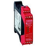
XPSAF5130P
Manufacturer Part Number
XPSAF5130P
Description
SAFETY RELAY 300V 2.5A PREVENTA
Manufacturer
SQUARE D
Datasheet
1.XPSMCCPC.pdf
(274 pages)
Specifications of XPSAF5130P
Contact Current Max
30mA
Contact Voltage Dc Nom
24V
Contact Configuration
3NO
Relay Mounting
DIN Rail
External Height
66mm
External Width
114mm
External Depth
22.5mm
Rohs Compliant
Yes


10
1
2
3
4
5
6
7
8
9
Operating principle,
characteristics
Product designed for max. use in safety related parts of
control systems (conforming to EN 60954-1/ISO 13849-1)
Conformity to standards
Product certifications
Supply
Power consumption
Module inputs fuse protection
Time delay
Pulse time
Outputs
Electrical life
Rated insulation voltage (Ui)
Rated impulse withstand voltage (Uimp.)
LED display
Operating temperature
Storage temperature
Degree of protection
conforming to IEC 60529
Connection
Principle:
page 2/230
2/230
Operating principle
Characteristics
Module type
Voltage
Voltage limits
Frequency
c 24
a 24 V
a 115
a 230 V
Voltage reference
Number and type of safety circuits
Number and type of additional
circuits
Breaking capacity in AC-15
Breaking capacity in DC-13
Breaking capacity of solid-state
outputs
Max. thermal current (Ithe)
Output fuse protection
Minimum current
Minimum voltage
1-wire
connection
2-wire
connection
Characteristics:
page 2/230
Terminals
Enclosure
Type
Without cable end
With cable end
With cable end
Without cable end
With cable end
With cable end
Safety automation system solutions
Preventa™ safety relay modules types
XPSTSA, XPSTSW
For safety time delays
Safety modules XPSTSA and XPSTSW are used in applications requiring safety
time delays:
b modules XPSTSA in applications with interlocking on high inertia machines with
long rundown time (guards unlocked after safety time delay has elapsed),
b modules XPSTSW in applications with a safety switchover contact (jumpering
contact in association with XPSVN modules for zero speed detection, solenoid valve
monitoring, etc.).
The time delay of safety circuits can be set to 16 preset values, using 2 selectors
located on the front cover of the modules.
To aid diagnostics, the modules have LEDs which provide information on the
monitoring circuit status and 2 solid-state outputs for signalling to the process PLC.
In addition, their removable terminal blocks optimize machine maintenance.
References:
page 2/231
V
Hz
VA
s
s
VA
A
A
mA
V
V
kV
°F (°C) + 14…+ 131 (- 10…+ 55)
°F (°C) - 13…+ 185 (- 25…+ 85)
XPSTSA
Category 3 max.
EN/IEC 60204-1, EN/IEC 60947-5-1
UL, CSA, BG
a and c 24, a 115, a 230
- 15…+ 15% (c 24 V)
- 20…+ 10% (a 24 V)
- 15…+ 15% (115 V)
- 15…+ 10% (230 V)
50/60
< 2.3
< 4.3
< 6.5
< 5.5
Internal, electronic
1…31 (16 positions)
–
Relay hard contacts
1 N.O. (17-18) + 2 N.C. (25-26, 35-36)
2 solid-state (Y53-Y54, Y63-Y64)
C300: inrush 1800, maintained 180
24 V/1.5 A - L/R = 50 ms
24 V/20 mA, 48 V/10 mA
6
4 gG (gl) or 6 fast acting, conforming to EN/IEC 60947-5-1, DIN VDE 0660 part 200
10
17
See page 2/172
300 (degree of pollution 2 conforming to EN/IEC 60947-5-1, DIN VDE 0110 parts 1 & 2)
4 (overvoltage category III, conforming to EN/IEC 60947-5-1, DIN VDE 0110 parts 1 & 2)
4
IP 20
IP 40
Captive screw clamp terminals, removable terminal block
Solid or flexible cable: 24-14 AWG (0.2…2.5 mm
Without bezel, flexible cable: 24-14 AWG (0.25…2.5 mm
With bezel, flexible cable: 24-14 AWG (0.25…2.5 mm
Solid cable: 24-18 AWG (0.2…1 mm
Without bezel, flexible cable: 24-18 AWG (0.25…1 mm
Double, with bezel, flexible cable: 20-16 AWG (0.5…1.5 mm
Wiring Diagrams:
page 2/231
2
), flexible cable: 24-16 AWG (0.2…1.5 mm
XPSTSW
–
0.1…3.1 (16 positions)
2
)
2
)
2
)
2
Dimensions:
page 2/260
)
2
)
2
)
0
Related parts for XPSAF5130P
Image
Part Number
Description
Manufacturer
Datasheet
Request
R


Part Number:
Description:
Pushbutton, Non-Illum'd Red "STOP", Momentary, 1NO-1NC, Square 30mm, 10A, 600V
Manufacturer:
SQUARE D
Datasheet:

Part Number:
Description:
KITS,TWIDO? PROGRAMMABLE CONTROLLERS,KITS,TWIDOPACK STARTER KIT - ADVANCED LEVEL,PROGRAMMABLE CONTROLLERS,TWIDO? PROGRAMMABLE CONTROLLERS ,SQUARE D
Manufacturer:
SQUARE D

Part Number:
Description:
LAMPS,INDICATOR,STACKABLE,LAMPS, STACKABLE INDICATOR,VISUAL INDICATING SIGNALS,XVB SERIES INDICATING BANKS ,SQUARE D
Manufacturer:
SQUARE D
Part Number:
Description:
LAMPS,INDICATOR,STACKABLE,LAMPS, STACKABLE INDICATOR,VISUAL INDICATING SIGNALS,XVB SERIES INDICATING BANKS ,SQUARE D
Manufacturer:
SQUARE D
Datasheet:
Part Number:
Description:
I/O EXTENDER MODULE 4 D IN & 2 D OUTPUT
Manufacturer:
SQUARE D
Datasheet:
Part Number:
Description:
CB ACCESSORY, UNDERVOLTAGE TRIP 48V DC
Manufacturer:
SQUARE D
Datasheet: