XPSAF5130P SQUARE D, XPSAF5130P Datasheet - Page 157
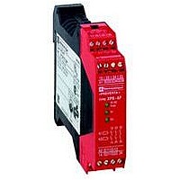
XPSAF5130P
Manufacturer Part Number
XPSAF5130P
Description
SAFETY RELAY 300V 2.5A PREVENTA
Manufacturer
SQUARE D
Datasheet
1.XPSMCCPC.pdf
(274 pages)
Specifications of XPSAF5130P
Contact Current Max
30mA
Contact Voltage Dc Nom
24V
Contact Configuration
3NO
Relay Mounting
DIN Rail
External Height
66mm
External Width
114mm
External Depth
22.5mm
Rohs Compliant
Yes


10
10
1
1
2
2
3
3
4
4
5
5
6
6
7
7
8
8
9
9
Wiring diagrams
Category 4 conforming to standard EN 954-1.
a
+
0 V
S8: Operating modes:
0 - stop,
1 - adjust,
2 - jog,
3 - automatic continuous run.
OTS = Limit switch associated with top dead center (TDC)
UN = Limit switch associated with bottom dead center (BDC)
PSV = safety valve
B1 = sensor at tooth wheel in cam switch mechanism.
(1) Technical characteristics for maximum rating of fuses, see page 2/122.
(2) Only applicable to XPSMC32Zp (I17…I32).
Presentation:
page 2/118
N
2/156
Eccentric press
Wiring diagram
24 V
230 V
F1
(1)
A1
A2
C8
T
C7 C6 C5 C4 C3 C2 C1
24 V
5 V
Logic
Characteristics:
page 2/122
GND
B1
I1
(2)
(continued)
S9
GND
A
+
–
I17
µC 1
µC 2
GND
2
4
1
S10
I2
Valve control
I18
(Y1a)
PSV 1
Mush-
room
head 1
K0
Chnl. 1
Chnl. 2
S1
NO
P
I3
Mush-
room
head 2
NC
Y1
PSV 1
I19
O1
a
I4
S2
NO
Safety automation system solutions
Preventa™ configurable safety controllers
Type XPSMC
References:
page 2/124
Chnl. 1
Chnl. 2
I20
I5
NC
Emer.
stop
XPS MC
PSV 2
S3
I21
b
O2
I6
I22
OTS
Chnl. 1
Chnl. 2
I7
S4
Valve control
P
I23
PSV 2
(Y1b)
I8
O3
I24
UN
Sub-D 9
S5
I9
2
4
1
Chnl. 1
Chnl. 2
I25
PSV1
I10
(Y1a)
Dimensions:
page 2/125
P >
I26
Ter
I11
O4
Chnl. 1
Chnl. 2
PSV2
Continuous
deactivated
(Y1b)
I27
P >
function
I12
I28
O5
I13
Chnl. 1
Chnl. 2
S6
I29
I14
S7
I30
O6
I15
Reset
S8
I31
K1
K2
I16
Wiring Diagrams:
page 2/126
0
1 2
I32
3
13
14 24
OFF-Stop
ON-Run
2
23
1
K3
K4
SM1
SM2
FM1
KM1
4
H1
3
a
33 43
34 44
6
(1)
+
5
F2
KM1
230 V
24 V
0 V
N
Related parts for XPSAF5130P
Image
Part Number
Description
Manufacturer
Datasheet
Request
R


Part Number:
Description:
Pushbutton, Non-Illum'd Red "STOP", Momentary, 1NO-1NC, Square 30mm, 10A, 600V
Manufacturer:
SQUARE D
Datasheet:

Part Number:
Description:
KITS,TWIDO? PROGRAMMABLE CONTROLLERS,KITS,TWIDOPACK STARTER KIT - ADVANCED LEVEL,PROGRAMMABLE CONTROLLERS,TWIDO? PROGRAMMABLE CONTROLLERS ,SQUARE D
Manufacturer:
SQUARE D

Part Number:
Description:
LAMPS,INDICATOR,STACKABLE,LAMPS, STACKABLE INDICATOR,VISUAL INDICATING SIGNALS,XVB SERIES INDICATING BANKS ,SQUARE D
Manufacturer:
SQUARE D
Part Number:
Description:
LAMPS,INDICATOR,STACKABLE,LAMPS, STACKABLE INDICATOR,VISUAL INDICATING SIGNALS,XVB SERIES INDICATING BANKS ,SQUARE D
Manufacturer:
SQUARE D
Datasheet:
Part Number:
Description:
I/O EXTENDER MODULE 4 D IN & 2 D OUTPUT
Manufacturer:
SQUARE D
Datasheet:
Part Number:
Description:
CB ACCESSORY, UNDERVOLTAGE TRIP 48V DC
Manufacturer:
SQUARE D
Datasheet: