XPSAF5130P SQUARE D, XPSAF5130P Datasheet - Page 253
XPSAF5130P
Manufacturer Part Number
XPSAF5130P
Description
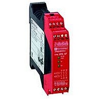
SAFETY RELAY 300V 2.5A PREVENTA
Manufacturer
SQUARE D
Datasheet
1.XPSMCCPC.pdf
(274 pages)
Specifications of XPSAF5130P
Contact Current Max
30mA
Contact Voltage Dc Nom
24V
Contact Configuration
3NO
Relay Mounting
DIN Rail
External Height
66mm
External Width
114mm
External Depth
22.5mm
Rohs Compliant
Yes


10
1
2
3
4
5
6
7
8
9
Operating principle,
characteristics
Product designed for max. use in safety related parts of
control systems (conforming to EN 954-1/ISO 13849-1)
Conformity to standards
Product certifications
Supply
Power consumption
Outputs
Response time
Electrical life
Rated insulation voltage (Ui)
Rated impulse withstand voltage (Uimp.)
LED display
Operating temperature
Storage temperature
Degree of protection
Conforming to IEC 60529
Polycarbonate
enclosure
Connection
Principle:
page 2/252
2/252
Operating principle
Characteristics
Module type
Voltage
Voltage limits
Frequency
c 24 V
a 115 V/230 V
Voltage reference
Number and type of safety circuits
Number and type of additional circuits
Breaking capacity in AC-15
Breaking capacity in DC-13
Max. thermal current (Ithe)
Breaking capacity of solid-state
outputs
Output fuse protection
Minimum current (relay hard contacts) mA
Minimum voltage (relay hard contacts) V
Terminals
Enclosure
Type
Number of terminals
Type
Characteristics:
page 2/252
Safety automation system solutions
Preventa™ safety relay modules type XPSPVK
For dynamic monitoring of double-bodied solenoid valves
Safety module XPSPVK is specially designed for dynamic monitoring of the safety
valves in eccentric presses, conforming to European standard EN 692.
This standard establishes the specifications related to safety control systems for
presses equipped with friction clutches.
To meet the requirements of this standard, the clutch/brake control must be
monitored dynamically.
This function is provided by a double-bodied solenoid valve (safety valve for presses)
which performs the functions of two valves mounted in one body.
The position of the two valve pistons can be monitored by proximity sensors,
mechanical limit switches or pressure switches.
Module XPSPVK checks for the correct operation of the double-bodied safety valves
at 3 points in the cycle.
b Start at top dead center: checks the rest position of the two valves.
b Take-on point (transfer function): checks that the two valves are in the “activated”
(energized) position.
b Press stop trigger point: checks that the two valves return to the rest position.
Return must be simultaneous for both valves within a defined time period.
To set up an automatic disconnect of the XPSPVK module at the first machine
stroke, a N.C. auxiliary contact mounted on the main control contactor or on another
contactor/relay, activated at the same time, can be wired to terminals 7 and 8 in
parallel with the RESET button.
If an anomaly is detected during the cycle, the XPSPVK module will stop the slide
stroke and will also inhibit the start of another cycle.
References:
page 2/253
V
Hz
W
VA
VA
A
A
ms
V
kV
°F (°C) + 14…+ 131 (- 10…+ 55)
°F (°C) - 13…+ 185 (- 25…+ 85)
XPSPVK
Category 4 max.
EN 60204-1, EN/IEC 60947-5-1, EN 692, EN 50082-2
UL, CSA
c 24, a115, a 230
- 10…+ 10% (c 24 V)
- 15…+ 15% (a 115 V)
- 15…+ 10% (a 230 V)
50/60
< 9
< 16
Relay hard contacts
1 N.O. (13-14) transfer function + 1 N.C. (21-22) feedback loop
4 solid-state outputs
C300: inrush 1800, maintained 180
24 V/1.5 A - L/R = 50 ms
2.5
24 V/20 mA, 48 V/10 mA
4 gG, conforming to EN/IEC 60947-5-1, VDE 0660 part 200
10
17
< 40
See page 2/172
300 (degree of pollution 2 conforming to EN/IEC 60947-5-1, DIN VDE 0110 parts 1 & 2)
4 (overvoltage category III, conforming to EN/IEC 60947-1, DIN VDE 0110 parts 1 & 2)
8
IP 20
IP 40
Removable
32
Captive screw clamp terminals: without cable end 2 x14 AWG (2 x 2.5 mm
cable end 2 x16 AWG (2 x 1.5 mm
Wiring Diagrams:
page 2/253
2
), min. Ø 0.5 mm
Dimensions:
page 2/260
2
), with
1
Related parts for XPSAF5130P
Image
Part Number
Description
Manufacturer
Datasheet
Request
R


Part Number:
Description:
Pushbutton, Non-Illum'd Red "STOP", Momentary, 1NO-1NC, Square 30mm, 10A, 600V
Manufacturer:
SQUARE D
Datasheet:

Part Number:
Description:
KITS,TWIDO? PROGRAMMABLE CONTROLLERS,KITS,TWIDOPACK STARTER KIT - ADVANCED LEVEL,PROGRAMMABLE CONTROLLERS,TWIDO? PROGRAMMABLE CONTROLLERS ,SQUARE D
Manufacturer:
SQUARE D

Part Number:
Description:
LAMPS,INDICATOR,STACKABLE,LAMPS, STACKABLE INDICATOR,VISUAL INDICATING SIGNALS,XVB SERIES INDICATING BANKS ,SQUARE D
Manufacturer:
SQUARE D
Part Number:
Description:
LAMPS,INDICATOR,STACKABLE,LAMPS, STACKABLE INDICATOR,VISUAL INDICATING SIGNALS,XVB SERIES INDICATING BANKS ,SQUARE D
Manufacturer:
SQUARE D
Datasheet:
Part Number:
Description:
I/O EXTENDER MODULE 4 D IN & 2 D OUTPUT
Manufacturer:
SQUARE D
Datasheet:
Part Number:
Description:
CB ACCESSORY, UNDERVOLTAGE TRIP 48V DC
Manufacturer:
SQUARE D
Datasheet: