XPSAF5130P SQUARE D, XPSAF5130P Datasheet - Page 40
XPSAF5130P
Manufacturer Part Number
XPSAF5130P
Description
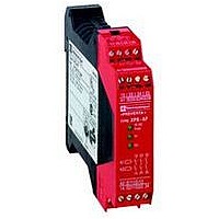
SAFETY RELAY 300V 2.5A PREVENTA
Manufacturer
SQUARE D
Datasheet
1.XPSMCCPC.pdf
(274 pages)
Specifications of XPSAF5130P
Contact Current Max
30mA
Contact Voltage Dc Nom
24V
Contact Configuration
3NO
Relay Mounting
DIN Rail
External Height
66mm
External Width
114mm
External Depth
22.5mm
Rohs Compliant
Yes


Description
1
3
4
2
8
1
2
7
5
6
3 4
6
10
7
8
9
5
Safety automation system solutions
Preventa™ safety PLCs
Modular, XPSMF60
Rack, power supply and CPU
Modular assembly consisting of:
1 A metal rack XPSMFGEH01.
2 A c 24 V power supply module XPSMFPS01.
3 A central processing unit XPSMFCPU22.
4 Six optional “in rack” I/O cards (back plane bus assures the electrical connection
5 A metal plate for securing shielded analog input connection cables (EMC),
6 One ground connection screw.
7 Two cooling fans (beneath the metal rack).
8 Four Ø 0.55 in (14 mm) elongated holes for mounting the rack on a vertical
Power supply module XPSMFPS01 and Central processing unit XPSMFCPU22
consisting of:
1 Four voltage status LEDs (FAULT, 24 V, 3.3 V or 5 V).
2 A RESTART button (accessible using fine pointed tool).
3 A 3-pole terminal block (3 captive screws) for “Fault contact” function
4 A c 24 V supply terminal block, including ground connection
5 A grip to assist installation/removal of the power supply module.
6 Seven process status LEDs.
7 Four integrated RJ45 (type 10BASE-T/100BASE-TX) switched ports for
8 Two process status LEDs.
9 A SUB-D 9-pin connector (FB2) for connection on Modbus® serial (RTU) (FB1 not
10 A grip to assist installation/removal of the CPU.
(1) “Fault contact” function: the power supply module incorporates a volt-free changeover
contact. Operating errors occurring in the system are read and displayed by the LEDs. The errors
are analyzed on the programming PC:
(2) Removable screw terminal blocks are provided with the power supply and “in rack” I/O cards.
01
02
03 FAULT
Description
Modular safety PLC
of “in rack” cards installed, the power supply module and the CPU).
support.
Programming, and for Safety and non-safety related communication on Ethernet.
(safety related using SafeEthernet protocol and Non-safety related using
Modbus® TCP server protocol).
used), with process status LED.
Contact positions
1-2 closed (2-3 open)
1-2 open (2-3 closed)
Status
Normal operation of the PLC.
Absence of supply to the PLC or the CPU is in
ERROR STOP mode.
(2)
.
(1)
.
2/39
10
10
1
1
2
2
3
3
4
4
5
5
6
6
7
7
8
8
9
9
Related parts for XPSAF5130P
Image
Part Number
Description
Manufacturer
Datasheet
Request
R


Part Number:
Description:
Pushbutton, Non-Illum'd Red "STOP", Momentary, 1NO-1NC, Square 30mm, 10A, 600V
Manufacturer:
SQUARE D
Datasheet:

Part Number:
Description:
KITS,TWIDO? PROGRAMMABLE CONTROLLERS,KITS,TWIDOPACK STARTER KIT - ADVANCED LEVEL,PROGRAMMABLE CONTROLLERS,TWIDO? PROGRAMMABLE CONTROLLERS ,SQUARE D
Manufacturer:
SQUARE D

Part Number:
Description:
LAMPS,INDICATOR,STACKABLE,LAMPS, STACKABLE INDICATOR,VISUAL INDICATING SIGNALS,XVB SERIES INDICATING BANKS ,SQUARE D
Manufacturer:
SQUARE D
Part Number:
Description:
LAMPS,INDICATOR,STACKABLE,LAMPS, STACKABLE INDICATOR,VISUAL INDICATING SIGNALS,XVB SERIES INDICATING BANKS ,SQUARE D
Manufacturer:
SQUARE D
Datasheet:
Part Number:
Description:
I/O EXTENDER MODULE 4 D IN & 2 D OUTPUT
Manufacturer:
SQUARE D
Datasheet:
Part Number:
Description:
CB ACCESSORY, UNDERVOLTAGE TRIP 48V DC
Manufacturer:
SQUARE D
Datasheet: