XPSAF5130P SQUARE D, XPSAF5130P Datasheet - Page 204
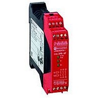
XPSAF5130P
Manufacturer Part Number
XPSAF5130P
Description
SAFETY RELAY 300V 2.5A PREVENTA
Manufacturer
SQUARE D
Datasheet
1.XPSMCCPC.pdf
(274 pages)
Specifications of XPSAF5130P
Contact Current Max
30mA
Contact Voltage Dc Nom
24V
Contact Configuration
3NO
Relay Mounting
DIN Rail
External Height
66mm
External Width
114mm
External Depth
22.5mm
Rohs Compliant
Yes


Wiring diagrams
Automatic start, without synchronization time monitoring
L
N
Supply connection according to voltage: a across terminals A1/A2, or c 24 V across terminals B1/B2.
(1) Operating status of internal electronic fuse.
ESC: External start conditions.
Principle:
page 2/200
XPSAK
Monitoring of a movable guard associated with 2 switches with 1 contact each in combined mode (switch 1 with N.O. contact, switch 2 with N.C. contact)
Monitoring of a movable guard associated with 2 switches and automatic start
(shown with guard open)
Module XPSAK associated with an Emergency stop button with 2 N.C. contacts
A2
A2
A1
A1
F1
XPS AK
XPS AK
B2
B2
B1
B1
A2
A1
XPS AK
+
(+24 V)
S21
S21
S11
S11
( )
B1
S2
B2
S1
Guard closed
S11
S21
Input A
S22
S22
S12
S12
Characteristics:
page 2/200
S2
S1
S12
S22
S31
S31
S31
(continued)
Logic
Input B
Start
S1
S2
S1
S32
S32
S32
S33
S13
S13
S13
S33
K3
K4
S34
S14
ESC
S14
S14
S34
K1
K2
K3
Safety automation system solutions
Preventa™ safety relay modules type XPSAK
For Emergency stop, switch, sensing mat/edges or light
curtain monitoring
13
14
References:
page 2/201
K4
23
24
Manual start by Start button
For synchronization monitoring of the inputs, S13 and S14 must be wired per the
diagram to the left (if S13 and S14 are jumpered, the result would be automatic
start without synchronization monitoring). The synchronization time is
determined by the first limit switch that is activated.
If S1 is actuated before S2, then the synchronization time is two seconds
on closing.
If S2 is actuated before S1, then the synchronization time is four seconds
on closing.
There is no synchronization on opening the door or guard.
Functional diagram of outputs
S2
Outputs
S1
33
34
A2
A1
XPS AK
2 s
41
42
B2
B1
Input
A
Y31
Wiring Diagrams:
page 2/202
K1/K2
S11
S21
S2
Y64
Y32
Guard closed
To PLC
Input
To PLC
B
S22
4 s
S12
Fuse
(1)
S31
Y74
Y54
S1
S32
Start
S2
S33
S13
Dimensions:
page 2/260
S34
S14
2/203
10
10
1
1
2
2
3
3
4
4
5
5
6
6
7
7
8
8
9
9
Related parts for XPSAF5130P
Image
Part Number
Description
Manufacturer
Datasheet
Request
R


Part Number:
Description:
Pushbutton, Non-Illum'd Red "STOP", Momentary, 1NO-1NC, Square 30mm, 10A, 600V
Manufacturer:
SQUARE D
Datasheet:

Part Number:
Description:
KITS,TWIDO? PROGRAMMABLE CONTROLLERS,KITS,TWIDOPACK STARTER KIT - ADVANCED LEVEL,PROGRAMMABLE CONTROLLERS,TWIDO? PROGRAMMABLE CONTROLLERS ,SQUARE D
Manufacturer:
SQUARE D

Part Number:
Description:
LAMPS,INDICATOR,STACKABLE,LAMPS, STACKABLE INDICATOR,VISUAL INDICATING SIGNALS,XVB SERIES INDICATING BANKS ,SQUARE D
Manufacturer:
SQUARE D
Part Number:
Description:
LAMPS,INDICATOR,STACKABLE,LAMPS, STACKABLE INDICATOR,VISUAL INDICATING SIGNALS,XVB SERIES INDICATING BANKS ,SQUARE D
Manufacturer:
SQUARE D
Datasheet:
Part Number:
Description:
I/O EXTENDER MODULE 4 D IN & 2 D OUTPUT
Manufacturer:
SQUARE D
Datasheet:
Part Number:
Description:
CB ACCESSORY, UNDERVOLTAGE TRIP 48V DC
Manufacturer:
SQUARE D
Datasheet: