XPSAF5130P SQUARE D, XPSAF5130P Datasheet - Page 183
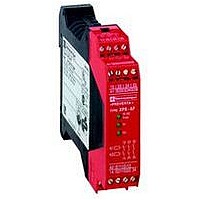
XPSAF5130P
Manufacturer Part Number
XPSAF5130P
Description
SAFETY RELAY 300V 2.5A PREVENTA
Manufacturer
SQUARE D
Datasheet
1.XPSMCCPC.pdf
(274 pages)
Specifications of XPSAF5130P
Contact Current Max
30mA
Contact Voltage Dc Nom
24V
Contact Configuration
3NO
Relay Mounting
DIN Rail
External Height
66mm
External Width
114mm
External Depth
22.5mm
Rohs Compliant
Yes


10
10
1
1
2
2
3
3
4
4
5
5
6
6
7
7
8
8
9
9
Wiring diagrams
(1) Instantaneous opening safety outputs (stop category 0).
(2) Time delay opening safety outputs (stop category 1).
ESC = External start conditions.
Note: Automatic start function is not available on the XPSAV with 2 channel wiring on the inputs. Automatic start function is only available on single channel wiring
on the inputs.
Monitored start
Linked input
S11-S12
Emergency stop
(channel 1) S21-S22
Emergency stop
(channel 2) S31-S32
Start button
S33-S34
Time delay interrupt
Y39-Y40
N.O. output
03-04/13-14/23-24
N.O. output
37-38/47-48/57-58
Signalling output
Y74
Signalling output
Y84
1-channel wiring
Principle:
page 2/178
A1
A2
2/182
XPSAV
Module XPSAV associated with an Emergency stop button with 2 N.C. contacts, monitored start
Functional diagram
Emergency stop monitoring function configuration
XPS AV
S11
S21
S1
Power-up
S22
S12
Emergency
stop
Start
S31
start-up
Emergency stop
No
not activated
Emergency
Characteristics:
page 2/178
S32
Logic
channel 1
Logic
channel 2
Start
(continued)
stop
Tv = 0…300 s
Output 1
Output 1
Output 2
Emergency stop
Output 2
Time delay stop
activated
Safety automation system solutions
Preventa™ safety relay modules type XPSAV
For Emergency stop and switch monitoring
References:
page 2/180
Emergency stop
not activated
Start
2-channel wiring, with short-circuit detection
stop activated
Time delay
interrupted
Emergency
A1
A2
XPS AV
S11
S21
Wiring Diagrams:
page 2/181
S22
S12
To PLC
S31
S1
S32
Dimensions:
page 2/260
Related parts for XPSAF5130P
Image
Part Number
Description
Manufacturer
Datasheet
Request
R


Part Number:
Description:
Pushbutton, Non-Illum'd Red "STOP", Momentary, 1NO-1NC, Square 30mm, 10A, 600V
Manufacturer:
SQUARE D
Datasheet:

Part Number:
Description:
KITS,TWIDO? PROGRAMMABLE CONTROLLERS,KITS,TWIDOPACK STARTER KIT - ADVANCED LEVEL,PROGRAMMABLE CONTROLLERS,TWIDO? PROGRAMMABLE CONTROLLERS ,SQUARE D
Manufacturer:
SQUARE D

Part Number:
Description:
LAMPS,INDICATOR,STACKABLE,LAMPS, STACKABLE INDICATOR,VISUAL INDICATING SIGNALS,XVB SERIES INDICATING BANKS ,SQUARE D
Manufacturer:
SQUARE D
Part Number:
Description:
LAMPS,INDICATOR,STACKABLE,LAMPS, STACKABLE INDICATOR,VISUAL INDICATING SIGNALS,XVB SERIES INDICATING BANKS ,SQUARE D
Manufacturer:
SQUARE D
Datasheet:
Part Number:
Description:
I/O EXTENDER MODULE 4 D IN & 2 D OUTPUT
Manufacturer:
SQUARE D
Datasheet:
Part Number:
Description:
CB ACCESSORY, UNDERVOLTAGE TRIP 48V DC
Manufacturer:
SQUARE D
Datasheet: