XPSAF5130P SQUARE D, XPSAF5130P Datasheet - Page 258
XPSAF5130P
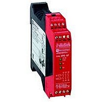
Manufacturer Part Number
XPSAF5130P
Description
SAFETY RELAY 300V 2.5A PREVENTA
Manufacturer
SQUARE D
Datasheet
1.XPSMCCPC.pdf
(274 pages)
Specifications of XPSAF5130P
Contact Current Max
30mA
Contact Voltage Dc Nom
24V
Contact Configuration
3NO
Relay Mounting
DIN Rail
External Height
66mm
External Width
114mm
External Depth
22.5mm
Rohs Compliant
Yes


Operating principle
(continued)
Principle:
page 2/258
Operating principle
Press diagram
Top Dead
Center
Bottom Dead
Center
TDC
Die
(continued)
BDC
Characteristics:
page 2/258
Safety automation system solutions
Preventa™ safety relay modules type XPSOT
For safety stop with automatic overtravel monitoring
and control
1
2
3
S Permissible overtravel.
A Stop instruction trip point.
B Point at which permissible overtravel is exceeded (a stop instruction issued after
point B will lock up the press).
C Takeover point, beyond which the press will complete its cycle up to TDC.
TDC Top dead center, actual stopping zone of the press.
BDC Bottom dead center.
Cam operation
Cam 1 is associated with the OTS limit switch (LS), cam 2 with the UN limit switch
(the limit switches must be located on different cams for safety reasons).
The OTS limit switch is deactivated at TDC, at which point the UN limit switch is
activated.
Point A1 of cam 1 is located approximately 300° after TDC and, when reached, the
press stops and comes to a standstill: A1 is the press stop trigger point.
Point B1, located approximately 10° after TDC, constitutes the end of cam 1: If B1
is exceeded during stopping, the overtravel is abnormally long, the press locks
up and the next cycle is inhibited.
Point A2 of cam 2 functions like point A1 on cam 1 (contact state of the UN limit
switch reversed in relation to the state of the OTS limit switch).
Point C2, located approximately 150° after TDC, corresponds to the 8 mm tool
closing dimension. Stop instructions issued after C2 is reached are not executed
until point A2 is reached.
References:
page 2/258
Control cams diagram
Permissible overtravel zone.
Dangerous zone (usually slide downstroke).
Non-dangerous zone (usually slide upstroke).
TDC Stop and overtravel monitoring
approx.
approx.
Wiring Diagrams:
page 2/259
UN
Limit switch
OTS
Limit switch
Restart + Stop
Dimensions:
page 2/260
approx.
2/257
0
10
1
2
3
4
5
6
7
8
9
Related parts for XPSAF5130P
Image
Part Number
Description
Manufacturer
Datasheet
Request
R


Part Number:
Description:
Pushbutton, Non-Illum'd Red "STOP", Momentary, 1NO-1NC, Square 30mm, 10A, 600V
Manufacturer:
SQUARE D
Datasheet:

Part Number:
Description:
KITS,TWIDO? PROGRAMMABLE CONTROLLERS,KITS,TWIDOPACK STARTER KIT - ADVANCED LEVEL,PROGRAMMABLE CONTROLLERS,TWIDO? PROGRAMMABLE CONTROLLERS ,SQUARE D
Manufacturer:
SQUARE D

Part Number:
Description:
LAMPS,INDICATOR,STACKABLE,LAMPS, STACKABLE INDICATOR,VISUAL INDICATING SIGNALS,XVB SERIES INDICATING BANKS ,SQUARE D
Manufacturer:
SQUARE D
Part Number:
Description:
LAMPS,INDICATOR,STACKABLE,LAMPS, STACKABLE INDICATOR,VISUAL INDICATING SIGNALS,XVB SERIES INDICATING BANKS ,SQUARE D
Manufacturer:
SQUARE D
Datasheet:
Part Number:
Description:
I/O EXTENDER MODULE 4 D IN & 2 D OUTPUT
Manufacturer:
SQUARE D
Datasheet:
Part Number:
Description:
CB ACCESSORY, UNDERVOLTAGE TRIP 48V DC
Manufacturer:
SQUARE D
Datasheet: