XPSAF5130P SQUARE D, XPSAF5130P Datasheet - Page 179
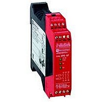
XPSAF5130P
Manufacturer Part Number
XPSAF5130P
Description
SAFETY RELAY 300V 2.5A PREVENTA
Manufacturer
SQUARE D
Datasheet
1.XPSMCCPC.pdf
(274 pages)
Specifications of XPSAF5130P
Contact Current Max
30mA
Contact Voltage Dc Nom
24V
Contact Configuration
3NO
Relay Mounting
DIN Rail
External Height
66mm
External Width
114mm
External Depth
22.5mm
Rohs Compliant
Yes


10
10
1
1
2
2
3
3
4
4
5
5
6
6
7
7
8
8
9
9
Product designed for max. use in safety related parts of
control systems (conforming to EN 954-1/EN/ISO 13849-1)
Conformity to standards
Product certifications
Supply
Power consumption
Module inputs fuse protection
Adjustable time delay
Start button monitoring
Control unit voltage
(at nominal supply voltage)
Calculation of wiring resistance RL between input terminals
Principle:
page 2/178
2/178
Operating principle
Characteristics
Module type
Operating principle,
characteristics
Voltage
Voltage limits
Frequency
24 V version
115 V, 230 V version
Characteristics:
page 2/178
Preventa™ Safety relay modules types XPSAV and XPSATE are used for monitoring
Emergency stop circuits conforming to standards EN/ISO 13850 and EN/IEC 60204-
1 and also meet the safety requirements for the electrical monitoring of switches in
protection devices (i.e.: safety interlock switches) conforming to standard EN 1088/
ISO 14119.
They provide protection for both the machine operator and the machine by
immediately stopping the machine movement on receipt of a stop instruction from
the operator, or on detection of an anomaly in the safety circuit itself.
In addition to the stop category 0 instantaneous opening safety outputs (3 for XPSAV
and 2 for XPSATE), the modules incorporate stop category 1 time delay outputs (3
for XPSAV and 3 for XPSATE) which allow for controlled deceleration of the motor
components until a complete stop is achieved (for example, motor braking by
variable speed drive).
At the end of the preset delay, the supply is disconnected by opening the time delay
output circuits.
For module XPSAV, the time delay of the 3 output circuits is adjustable, in 15 preset
values, between 0 and 300 seconds using selector buttons.
For module XPSATE, the time delay of the 3 output circuits is adjustable between 0
and 30 seconds using a 12-position selector switch.
Module XPSAV also incorporates 3 solid-state signalling outputs for signalling to the
process PLC. Module XPSATE incorporates 4 solid-state signalling outputs for
signalling to the process PLC.
To aid diagnostics, the modules have LEDs which provide information on the
monitoring circuit status.
The Start button monitoring function is configurable depending on the wiring.
References:
page 2/180
V
Hz
W
s
V
V
W
Safety automation system solutions
Preventa™ safety relay modules types
XPSAV, XPSATE
For Emergency stop and switch monitoring
XPSAV11113 and AV11113P
Category 4 max.
EN/IEC 60204-1, DIN V VDE 801 + A1,
EN/ISO 13850, EN 1088/ISO 14119,
EN/IEC 60947-1 A11, EN/IEC 60947-5-1
UL, CSA, BIA
c 24
- 20…+ 20%
–
< 5
Internal, electronic
0…300
Yes/No
(configurable by terminal connections)
Between input terminals S21-S22,
S31-S32 or S11-S12
24
–
100 max.
Maximum cable length: 6562 ft. (2000 m)
Wiring Diagrams:
page 2/181
XPSATEpppp and ATEppppP
Category 4 max. (instantaneous safety
outputs)
Category 3 max. (time delay safety
outputs)
EN/IEC 60204-1, EN/IEC 60947-5-1, EN/
ISO 13850, EN 50082-2
UL, CSA, BG
a and c 24,
a 115,
a 230
- 20…+ 10% (24 V)
- 15…+ 15% (115 V)
- 15…+ 10% (230 V)
50/60
< 8
Internal, electronic
0…30
Yes/No
(configurable by terminal connections)
Between input terminals S11-S12,
S21-S22 or S11-B1
24
48
RL max. =
Ue = true voltage applied to terminals
A1-A2
U int (terminals S11-S21) = supply voltage
Ue - 3 V (24 V version)
U int between 42 V and 45 V, with typical
value = 45 V (115 V, 230 V version)
Calculated max. RL must be equal to or
greater than the true value
U int - U min.
Dimensions:
page 2/260
I min.
Related parts for XPSAF5130P
Image
Part Number
Description
Manufacturer
Datasheet
Request
R


Part Number:
Description:
Pushbutton, Non-Illum'd Red "STOP", Momentary, 1NO-1NC, Square 30mm, 10A, 600V
Manufacturer:
SQUARE D
Datasheet:

Part Number:
Description:
KITS,TWIDO? PROGRAMMABLE CONTROLLERS,KITS,TWIDOPACK STARTER KIT - ADVANCED LEVEL,PROGRAMMABLE CONTROLLERS,TWIDO? PROGRAMMABLE CONTROLLERS ,SQUARE D
Manufacturer:
SQUARE D

Part Number:
Description:
LAMPS,INDICATOR,STACKABLE,LAMPS, STACKABLE INDICATOR,VISUAL INDICATING SIGNALS,XVB SERIES INDICATING BANKS ,SQUARE D
Manufacturer:
SQUARE D
Part Number:
Description:
LAMPS,INDICATOR,STACKABLE,LAMPS, STACKABLE INDICATOR,VISUAL INDICATING SIGNALS,XVB SERIES INDICATING BANKS ,SQUARE D
Manufacturer:
SQUARE D
Datasheet:
Part Number:
Description:
I/O EXTENDER MODULE 4 D IN & 2 D OUTPUT
Manufacturer:
SQUARE D
Datasheet:
Part Number:
Description:
CB ACCESSORY, UNDERVOLTAGE TRIP 48V DC
Manufacturer:
SQUARE D
Datasheet: