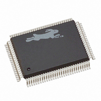
20-668-0003 Rabbit Semiconductor, 20-668-0003 Datasheet - Page 116

20-668-0003
Manufacturer Part Number
20-668-0003
Description
IC CPU RABBIT2000 30MHZ 100PQFP
Manufacturer
Rabbit Semiconductor
Datasheet
1.20-668-0003.pdf
(228 pages)
Specifications of 20-668-0003
Processor Type
Rabbit 2000 8-Bit
Speed
30MHz
Voltage
2.7V, 3V, 3.3V, 5V
Mounting Type
Surface Mount
Package / Case
100-MQFP, 100-PQFP
Data Bus Width
8 bit
Maximum Clock Frequency
30 MHz
Operating Supply Voltage
0 V to 5.5 V
Maximum Operating Temperature
+ 85 C
Mounting Style
SMD/SMT
Minimum Operating Temperature
- 40 C
Number Of Programmable I/os
40
Number Of Timers
8 & 10 bit
Lead Free Status / RoHS Status
Lead free / RoHS Compliant
Features
-
Lead Free Status / Rohs Status
Lead free / RoHS Compliant
Other names
20-668-0003
316-1062
316-1062
Available stocks
Company
Part Number
Manufacturer
Quantity
Price
Company:
Part Number:
20-668-0003
Manufacturer:
Rabbit Semiconductor
Quantity:
10 000
- Current page: 116 of 228
- Download datasheet (2Mb)
Compared to memory read/write cycles, which are each 2 or 3 clock cycles long respectively,
external I/O read/write cycles are always at least three clock cycles long.
The eight I/O bank control registers determine the number of I/O wait states applied to an
external I/O access within the zone controlled by each register even if the associated
strobes are not enabled.
The control over the generation of wait states is independent of whether or not the associ-
ated strobe in Port E is enabled. The upper 2 bits of each register determine the number of
wait states. The four choices are 1, 3, 7, or 15 wait states. On reset, the bits are cleared,
resulting in 15 wait states. The inhibit write function applies to both the Port E write
strobes and the /IOWR signal.
These control bits have no effect on the internal I/O space, which does not have wait states
associated with read or write access. Internal I/O read or write cycles are two clocks long.
The I/O strobes greatly simplify the interfacing of external devices. On reset, the upper 5
bits of each register are cleared. Parallel port E will not output these signals unless the
data-direction register bits are set for the desired output positions. In addition, the Port E
function register must be set to "1" for each position.
Each I/O bank is selected by the three most significant bits of the 16-bit I/O address.
Table 10-2 shows the relationship between the I/O control register and its corresponding
space in the 64K address space.
110
NOTE: Refer to Section 3.3.8 for a fix to a bug that manifests itself if an I/O instruction
Table 10-2. External I/O Register Address Range and Pin Mapping
(prefix IOI or IOE) is followed by one of 12 single-byte op codes that use HL as an
index register.
IB0CR
IB1CR
IB2CR
IB3CR
IB4CR
IB5CR
IB6CR
IB7CR
Control Register
Port E
PE0
PE1
PE2
PE3
PE4
PE5
PE6
PE7
Pin
I/O Address
000
001
010
011
100
101
110
111
A[15:13]
Rabbit 2000 Microprocessor User’s Manual
0x0000–0x1FFF
0x2000–0x3FFF
0x4000–0x5FFF
0x6000–0x7FFF
0x8000–0x9FFF
0xA000–0xBFFF
0xC000–0xDFFF
0xE000–0xFFFF
I/O Address
Range
Related parts for 20-668-0003
Image
Part Number
Description
Manufacturer
Datasheet
Request
R

Part Number:
Description:
IC CPU RABBIT4000 128-LQFP
Manufacturer:
Rabbit Semiconductor
Datasheet:

Part Number:
Description:
IC MPU RABIT3000A 55.5MHZ128LQFP
Manufacturer:
Rabbit Semiconductor
Datasheet:

Part Number:
Description:
Microprocessors - MPU Rabbit 3000 TFBGA Microprocessor
Manufacturer:
Rabbit Semiconductor

Part Number:
Description:
Microprocessors - MPU Rabbit 4000 LQFP Microprocessor
Manufacturer:
Rabbit Semiconductor

Part Number:
Description:
IC, I/O EXPANDER, 8BIT, 40MHZ, TQFP-64
Manufacturer:
Rabbit Semiconductor

Part Number:
Description:
SCRs 1.5A 200uA 400V Sensing
Manufacturer:
Littelfuse Inc
Datasheet:

Part Number:
Description:
CARD 6-RELAY SMARTSTAR SR9500
Manufacturer:
Rabbit Semiconductor
Datasheet:

Part Number:
Description:
WIRE-BOARD CONN RECEPTACLE, 6POS, 3.96MM
Manufacturer:
TE Connectivity
Datasheet:

Part Number:
Description:
ADAPTER 20 PIN .420" PLUGS(6PCS)
Manufacturer:
Logical Systems Inc.
Datasheet:

Part Number:
Description:
CONN BARRIER BLOCK .438" 20 POS
Manufacturer:
Cinch Connectors
Datasheet:

Part Number:
Description:
20 MODII 2PC HDR DR SHRD, ROHS
Manufacturer:
TE Connectivity
Datasheet:

Part Number:
Description:
WIRE-BOARD CONN RECEPTACLE, 6POS, 3.96MM
Manufacturer:
TE Connectivity
Datasheet:


