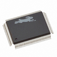
20-668-0003 Rabbit Semiconductor, 20-668-0003 Datasheet - Page 216

20-668-0003
Manufacturer Part Number
20-668-0003
Description
IC CPU RABBIT2000 30MHZ 100PQFP
Manufacturer
Rabbit Semiconductor
Datasheet
1.20-668-0003.pdf
(228 pages)
Specifications of 20-668-0003
Processor Type
Rabbit 2000 8-Bit
Speed
30MHz
Voltage
2.7V, 3V, 3.3V, 5V
Mounting Type
Surface Mount
Package / Case
100-MQFP, 100-PQFP
Data Bus Width
8 bit
Maximum Clock Frequency
30 MHz
Operating Supply Voltage
0 V to 5.5 V
Maximum Operating Temperature
+ 85 C
Mounting Style
SMD/SMT
Minimum Operating Temperature
- 40 C
Number Of Programmable I/os
40
Number Of Timers
8 & 10 bit
Lead Free Status / RoHS Status
Lead free / RoHS Compliant
Features
-
Lead Free Status / Rohs Status
Lead free / RoHS Compliant
Other names
20-668-0003
316-1062
316-1062
Available stocks
Company
Part Number
Manufacturer
Quantity
Price
Company:
Part Number:
20-668-0003
Manufacturer:
Rabbit Semiconductor
Quantity:
10 000
- Current page: 216 of 228
- Download datasheet (2Mb)
the gate input and allow the oscillator to operate at a lower voltage. This oscillator will
start at about 1.2 V and operate down to about 0.75 V. The 47 kΩ resistor limits the short-
circuit current when the CMOS gate is switching, and thus limits the overall current con-
sumption. The 330 kΩ resistor is needed to limit crystal drive at higher operating voltages,
but if the 330 kΩ resistor is too large, it will adversely affect low-voltage operation.
Typical 32.768 kHz crystals are specified for a maximum drive level of 1 µW. A modest
overdrive, perhaps 100% over this limit, will most likely have not any adverse effects
except to cause the crystal to age more rapidly than specified. Aging is a gradual change of
frequency of about 3 parts per million, and is most significant in the first few months of
operation. The drive power can be computed from P = (I
current and R is the effective resistance of the crystal. Typical values for R are 20 kΩ for
32.768 kHz turning-fork crystals. Maximum values are often specified as 35 kΩ or 50 kΩ.
If the effective resistance is 20 kΩ, then 1 µW of power is reached when I = 7 µA (RMS).
It is logical to use the typical effective resistance rather than the maximum total resistance
in computing drive power. If a particular crystal has a higher resistance, this indicates that
it is losing more energy on each oscillation, perhaps because of surface contamination, and
thus requires more power to sustain the same amplitude of physical flexure of the quartz.
Thus the stress on the quartz will not be greater even though the drive power is greater for
a unit that happens to have an effective resistance of 35 kΩ rather than the typical value of
20 kΩ. The current can be measured directly with a sensitive current probe, but it is easier
to calculate the current by measuring the voltage swing at the gate input with a low-capac-
itance oscilloscope probe. The RMS voltage at this point is related to the RMS current by
the relationship
where
If C
drive power (in µW) are given by
or
For a 5 V p-p swing, the power is 1.5 µW. The power is 1.0 µW for 4 V p-p, and the power is
0.5 µW for 3 V p-p.
TN235, External 32.768 kHz Oscillator Circuits, provides further information on oscilla-
tor circuits and crystals.
210
total
I = V
C
w = 2π * 32768
V
I = 2.5 * V
P = 0.125 * (V
I = 1.75 * V
P = 0.061 * (V
rms
total
= 12 pF, and the effective resistance is 20 kΩ, then the current (in µA) and the
rms
= 0.707 * V
= C2 + C
* w * C
rms
p-p
rms
p-p
i
total
+ C
p-p
)
)
2
2
probe
Rabbit 2000 Microprocessor User’s Manual
2
) * R, where I is the RMS AC
Related parts for 20-668-0003
Image
Part Number
Description
Manufacturer
Datasheet
Request
R

Part Number:
Description:
IC CPU RABBIT4000 128-LQFP
Manufacturer:
Rabbit Semiconductor
Datasheet:

Part Number:
Description:
IC MPU RABIT3000A 55.5MHZ128LQFP
Manufacturer:
Rabbit Semiconductor
Datasheet:

Part Number:
Description:
Microprocessors - MPU Rabbit 3000 TFBGA Microprocessor
Manufacturer:
Rabbit Semiconductor

Part Number:
Description:
Microprocessors - MPU Rabbit 4000 LQFP Microprocessor
Manufacturer:
Rabbit Semiconductor

Part Number:
Description:
IC, I/O EXPANDER, 8BIT, 40MHZ, TQFP-64
Manufacturer:
Rabbit Semiconductor

Part Number:
Description:
SCRs 1.5A 200uA 400V Sensing
Manufacturer:
Littelfuse Inc
Datasheet:

Part Number:
Description:
CARD 6-RELAY SMARTSTAR SR9500
Manufacturer:
Rabbit Semiconductor
Datasheet:

Part Number:
Description:
WIRE-BOARD CONN RECEPTACLE, 6POS, 3.96MM
Manufacturer:
TE Connectivity
Datasheet:

Part Number:
Description:
ADAPTER 20 PIN .420" PLUGS(6PCS)
Manufacturer:
Logical Systems Inc.
Datasheet:

Part Number:
Description:
CONN BARRIER BLOCK .438" 20 POS
Manufacturer:
Cinch Connectors
Datasheet:

Part Number:
Description:
20 MODII 2PC HDR DR SHRD, ROHS
Manufacturer:
TE Connectivity
Datasheet:

Part Number:
Description:
WIRE-BOARD CONN RECEPTACLE, 6POS, 3.96MM
Manufacturer:
TE Connectivity
Datasheet:


