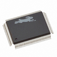
20-668-0003 Rabbit Semiconductor, 20-668-0003 Datasheet - Page 92

20-668-0003
Manufacturer Part Number
20-668-0003
Description
IC CPU RABBIT2000 30MHZ 100PQFP
Manufacturer
Rabbit Semiconductor
Datasheet
1.20-668-0003.pdf
(228 pages)
Specifications of 20-668-0003
Processor Type
Rabbit 2000 8-Bit
Speed
30MHz
Voltage
2.7V, 3V, 3.3V, 5V
Mounting Type
Surface Mount
Package / Case
100-MQFP, 100-PQFP
Data Bus Width
8 bit
Maximum Clock Frequency
30 MHz
Operating Supply Voltage
0 V to 5.5 V
Maximum Operating Temperature
+ 85 C
Mounting Style
SMD/SMT
Minimum Operating Temperature
- 40 C
Number Of Programmable I/os
40
Number Of Timers
8 & 10 bit
Lead Free Status / RoHS Status
Lead free / RoHS Compliant
Features
-
Lead Free Status / Rohs Status
Lead free / RoHS Compliant
Other names
20-668-0003
316-1062
316-1062
Available stocks
Company
Part Number
Manufacturer
Quantity
Price
Company:
Part Number:
20-668-0003
Manufacturer:
Rabbit Semiconductor
Quantity:
10 000
- Current page: 92 of 228
- Download datasheet (2Mb)
7.9.1 External Interrupts
There are two external interrupts. Because of a problem in the original Rabbit design, only
one of these interrupts is available for general use. The problem was corrected in revisions
A–C of the Rabbit 2000. (Refer to Appendix B for further information to determine which
version of the Rabbit 2000 chip you are using.) If you are working with an original Rabbit
2000 chip, see Technical Note 301, Rabbit 2000 Microprocessor Interrupt Problem.
External interrupts take place on a transition of the input. The pulse catchers are program-
mable separately to detect a rising, a falling, or both edges. The pairs of pulse catchers that
are connected to the same interrupt should be programmed for the same type of edge
detection. Each of the interrupt pins has its own catcher device to catch the edge transition
and request the interrupt. The pulse needs to be present for a least three peripheral clocks to
be detected.
When the interrupt takes place, both pulse catchers associated with that interrupt are auto-
matically reset. If both edges are detected before the corresponding interrupt takes place,
because the triggering edges occur nearly simultaneously or because the interrupts are
inhibited by the processor priority, then there will be only one interrupt for the two edges
detected. The interrupt service routine can read the interrupt pins via parallel port E and
determine which lines experienced a transition, provided that the transitions are not too
fast. Interrupts can also be generated by setting up the matching port E bit as an output and
toggling the bit.
86
I0CR
I1CR
Reg Name
10011000
10011001
Reg Address
Table 7-13. Control Registers for External Interrupts
xx
xx
Bits 7,6
INT0B PE4
INT1B PE5
edge triggered
00-disabled
10-rising
01-falling
11-both
Bits 5,4
Rabbit 2000 Microprocessor User’s Manual
INT0A PE0
INT1A PE1
edge triggered
00-disabled
10-rising
01-falling
11-both
Bits 3,2
Enb INT0
Enb INT1
interrupt
00-disable
01-pri 1
10-pri 2
11-pri 3
Bits 1,0
Related parts for 20-668-0003
Image
Part Number
Description
Manufacturer
Datasheet
Request
R

Part Number:
Description:
IC CPU RABBIT4000 128-LQFP
Manufacturer:
Rabbit Semiconductor
Datasheet:

Part Number:
Description:
IC MPU RABIT3000A 55.5MHZ128LQFP
Manufacturer:
Rabbit Semiconductor
Datasheet:

Part Number:
Description:
Microprocessors - MPU Rabbit 3000 TFBGA Microprocessor
Manufacturer:
Rabbit Semiconductor

Part Number:
Description:
Microprocessors - MPU Rabbit 4000 LQFP Microprocessor
Manufacturer:
Rabbit Semiconductor

Part Number:
Description:
IC, I/O EXPANDER, 8BIT, 40MHZ, TQFP-64
Manufacturer:
Rabbit Semiconductor

Part Number:
Description:
SCRs 1.5A 200uA 400V Sensing
Manufacturer:
Littelfuse Inc
Datasheet:

Part Number:
Description:
CARD 6-RELAY SMARTSTAR SR9500
Manufacturer:
Rabbit Semiconductor
Datasheet:

Part Number:
Description:
WIRE-BOARD CONN RECEPTACLE, 6POS, 3.96MM
Manufacturer:
TE Connectivity
Datasheet:

Part Number:
Description:
ADAPTER 20 PIN .420" PLUGS(6PCS)
Manufacturer:
Logical Systems Inc.
Datasheet:

Part Number:
Description:
CONN BARRIER BLOCK .438" 20 POS
Manufacturer:
Cinch Connectors
Datasheet:

Part Number:
Description:
20 MODII 2PC HDR DR SHRD, ROHS
Manufacturer:
TE Connectivity
Datasheet:

Part Number:
Description:
WIRE-BOARD CONN RECEPTACLE, 6POS, 3.96MM
Manufacturer:
TE Connectivity
Datasheet:


