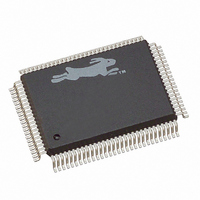
20-668-0003 Rabbit Semiconductor, 20-668-0003 Datasheet - Page 215

20-668-0003
Manufacturer Part Number
20-668-0003
Description
IC CPU RABBIT2000 30MHZ 100PQFP
Manufacturer
Rabbit Semiconductor
Datasheet
1.20-668-0003.pdf
(228 pages)
Specifications of 20-668-0003
Processor Type
Rabbit 2000 8-Bit
Speed
30MHz
Voltage
2.7V, 3V, 3.3V, 5V
Mounting Type
Surface Mount
Package / Case
100-MQFP, 100-PQFP
Data Bus Width
8 bit
Maximum Clock Frequency
30 MHz
Operating Supply Voltage
0 V to 5.5 V
Maximum Operating Temperature
+ 85 C
Mounting Style
SMD/SMT
Minimum Operating Temperature
- 40 C
Number Of Programmable I/os
40
Number Of Timers
8 & 10 bit
Lead Free Status / RoHS Status
Lead free / RoHS Compliant
Features
-
Lead Free Status / Rohs Status
Lead free / RoHS Compliant
Other names
20-668-0003
316-1062
316-1062
Available stocks
Company
Part Number
Manufacturer
Quantity
Price
Company:
Part Number:
20-668-0003
Manufacturer:
Rabbit Semiconductor
Quantity:
10 000
- Current page: 215 of 228
- Download datasheet (2Mb)
B.2.4 Improved Battery-Backup Circuit
Improvements were made in revisions A–C to reduce the internal power consumption of
the RTC circuit. In addition, external circuitry was designed to further reduce power con-
sumption by the overall oscillator circuit in board-level products based on the Rabbit
2000.
Low-Power Oscillator Design
An external low-current oscillator can be built using an inexpensive single-gate (tiny logic)
unbuffered inverter. The current consumption of this circuit is about 4 µA with a 2 V sup-
ply. Using this circuit, oscillation continues even when the voltage drops to 0.8 V, and
oscillation is still very strong at 1.2 V. The oscillator should have its exposed circuit traces
conformally coated to prevent the possibility of loading the circuit by conduction on the
PC board surface in a moist atmosphere. (Rabbit Semiconductor has published an applica-
tion note on conformal coating, Technical Note TN303, Conformal Coatings.)
The capacitors on either side of the crystal provide the load capacitance, which is specified
by the crystal manufacturer. Typically the load capacitance is about 12 pF. This is the
capacitance that should be in parallel with the crystal for it to operate at the specified fre-
quency. C1 and C2 provide this load capacitance. The formula for the load capacitance is
This is just the formula the capacitance of two capacitors in series plus any stray capaci-
tance in the board layout, perhaps 2 pF. Note that the input capacitance of the gate (C
must also be taken into account. The gate input capacitance is not constant, but is a func-
tion of frequency. Thus if it is measured, it should be done with a sine-wave generator
operating at 32 kHz. The output capacitance is not relevant because the 330 kΩ resistor
isolates it from the crystal. If C2 is made smaller, this will increase the voltage swing on
Appendix B Rabbit 2000 Revisions
C
L
=
(
-------------------------------------- -
C1
C1
+
) ∗ C2
(
(
C2
Figure B-1. Low-Power 32.768 kHz Oscillator Circuit
W
+
+
C
C
i
i
)
)
+
W
C
stray
W
W
in
)
209
Related parts for 20-668-0003
Image
Part Number
Description
Manufacturer
Datasheet
Request
R

Part Number:
Description:
IC CPU RABBIT4000 128-LQFP
Manufacturer:
Rabbit Semiconductor
Datasheet:

Part Number:
Description:
IC MPU RABIT3000A 55.5MHZ128LQFP
Manufacturer:
Rabbit Semiconductor
Datasheet:

Part Number:
Description:
Microprocessors - MPU Rabbit 3000 TFBGA Microprocessor
Manufacturer:
Rabbit Semiconductor

Part Number:
Description:
Microprocessors - MPU Rabbit 4000 LQFP Microprocessor
Manufacturer:
Rabbit Semiconductor

Part Number:
Description:
IC, I/O EXPANDER, 8BIT, 40MHZ, TQFP-64
Manufacturer:
Rabbit Semiconductor

Part Number:
Description:
SCRs 1.5A 200uA 400V Sensing
Manufacturer:
Littelfuse Inc
Datasheet:

Part Number:
Description:
CARD 6-RELAY SMARTSTAR SR9500
Manufacturer:
Rabbit Semiconductor
Datasheet:

Part Number:
Description:
WIRE-BOARD CONN RECEPTACLE, 6POS, 3.96MM
Manufacturer:
TE Connectivity
Datasheet:

Part Number:
Description:
ADAPTER 20 PIN .420" PLUGS(6PCS)
Manufacturer:
Logical Systems Inc.
Datasheet:

Part Number:
Description:
CONN BARRIER BLOCK .438" 20 POS
Manufacturer:
Cinch Connectors
Datasheet:

Part Number:
Description:
20 MODII 2PC HDR DR SHRD, ROHS
Manufacturer:
TE Connectivity
Datasheet:

Part Number:
Description:
WIRE-BOARD CONN RECEPTACLE, 6POS, 3.96MM
Manufacturer:
TE Connectivity
Datasheet:


