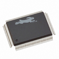
20-668-0003 Rabbit Semiconductor, 20-668-0003 Datasheet - Page 121

20-668-0003
Manufacturer Part Number
20-668-0003
Description
IC CPU RABBIT2000 30MHZ 100PQFP
Manufacturer
Rabbit Semiconductor
Datasheet
1.20-668-0003.pdf
(228 pages)
Specifications of 20-668-0003
Processor Type
Rabbit 2000 8-Bit
Speed
30MHz
Voltage
2.7V, 3V, 3.3V, 5V
Mounting Type
Surface Mount
Package / Case
100-MQFP, 100-PQFP
Data Bus Width
8 bit
Maximum Clock Frequency
30 MHz
Operating Supply Voltage
0 V to 5.5 V
Maximum Operating Temperature
+ 85 C
Mounting Style
SMD/SMT
Minimum Operating Temperature
- 40 C
Number Of Programmable I/os
40
Number Of Timers
8 & 10 bit
Lead Free Status / RoHS Status
Lead free / RoHS Compliant
Features
-
Lead Free Status / Rohs Status
Lead free / RoHS Compliant
Other names
20-668-0003
316-1062
316-1062
Available stocks
Company
Part Number
Manufacturer
Quantity
Price
Company:
Part Number:
20-668-0003
Manufacturer:
Rabbit Semiconductor
Quantity:
10 000
- Current page: 121 of 228
- Download datasheet (2Mb)
11.2 Timer B
Figure 11-1 shows a block diagram of Timer B.
The main clock for Timer B is
/2. Bit 0 of the TBCSR register controls the main clock
PCLK
for Timer B. The Timer B counter can be driven directly by
/2,
/16 [(
/2)/8],
PCLK
PCLK
PCLK
or by the output of Timer A1. The first two options are controlled by bit 0 in TBCSR. The
third option has to be enabled or disabled through bit 0 of the TACSR register.
Timer B has a continuously running 10-bit counter. The counter is compared against two
match registers, the B1 match register and the B2 match register. When the counter transi-
tions to a value equal to a match register, an internal pulse with a length of 1 peripheral
clock is generated. The match pulse can be used to cause interrupts and/or clock the output
registers of parallel ports D and E.
There are two ways to set up the Timer B match registers for use, one just after power-up,
and one for after using the Timer B match register system.
After power-up or reset, the value in the TBLxR match register is flagged as "invalid." At
this time a value written to the holding register will be transferred to the match register on
the next rising edge of the Timer B clock. Once the value is loaded in the match register,
an internal flag will indicate that a valid value is present in the match register. If another
value is written to the same register, it will stay in the holding register. Once a match
occurs, the value in the TBLxR match register is flagged as “invalid.” At that time, if a
value is in the holding register, it will get transferred to the match register, assuming that
the Timer B clock is running.
Every time a match condition occurs, the processor sets an internal bit that marks the match
value in TBLxR as invalid. Reading TBCSR clears the interrupt condition. TBLxR must
be reloaded to re-enable the interrupt. TBMxR does not need to be reloaded every time.
If both match registers need to be changed, the most significant byte needs to be changed first.
Chapter 11 Timers
115
Related parts for 20-668-0003
Image
Part Number
Description
Manufacturer
Datasheet
Request
R

Part Number:
Description:
IC CPU RABBIT4000 128-LQFP
Manufacturer:
Rabbit Semiconductor
Datasheet:

Part Number:
Description:
IC MPU RABIT3000A 55.5MHZ128LQFP
Manufacturer:
Rabbit Semiconductor
Datasheet:

Part Number:
Description:
Microprocessors - MPU Rabbit 3000 TFBGA Microprocessor
Manufacturer:
Rabbit Semiconductor

Part Number:
Description:
Microprocessors - MPU Rabbit 4000 LQFP Microprocessor
Manufacturer:
Rabbit Semiconductor

Part Number:
Description:
IC, I/O EXPANDER, 8BIT, 40MHZ, TQFP-64
Manufacturer:
Rabbit Semiconductor

Part Number:
Description:
SCRs 1.5A 200uA 400V Sensing
Manufacturer:
Littelfuse Inc
Datasheet:

Part Number:
Description:
CARD 6-RELAY SMARTSTAR SR9500
Manufacturer:
Rabbit Semiconductor
Datasheet:

Part Number:
Description:
WIRE-BOARD CONN RECEPTACLE, 6POS, 3.96MM
Manufacturer:
TE Connectivity
Datasheet:

Part Number:
Description:
ADAPTER 20 PIN .420" PLUGS(6PCS)
Manufacturer:
Logical Systems Inc.
Datasheet:

Part Number:
Description:
CONN BARRIER BLOCK .438" 20 POS
Manufacturer:
Cinch Connectors
Datasheet:

Part Number:
Description:
20 MODII 2PC HDR DR SHRD, ROHS
Manufacturer:
TE Connectivity
Datasheet:

Part Number:
Description:
WIRE-BOARD CONN RECEPTACLE, 6POS, 3.96MM
Manufacturer:
TE Connectivity
Datasheet:


