20-668-0003 Rabbit Semiconductor, 20-668-0003 Datasheet - Page 59
20-668-0003
Manufacturer Part Number
20-668-0003
Description
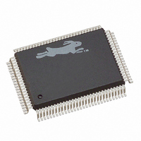
IC CPU RABBIT2000 30MHZ 100PQFP
Manufacturer
Rabbit Semiconductor
Datasheet
1.20-668-0003.pdf
(228 pages)
Specifications of 20-668-0003
Processor Type
Rabbit 2000 8-Bit
Speed
30MHz
Voltage
2.7V, 3V, 3.3V, 5V
Mounting Type
Surface Mount
Package / Case
100-MQFP, 100-PQFP
Data Bus Width
8 bit
Maximum Clock Frequency
30 MHz
Operating Supply Voltage
0 V to 5.5 V
Maximum Operating Temperature
+ 85 C
Mounting Style
SMD/SMT
Minimum Operating Temperature
- 40 C
Number Of Programmable I/os
40
Number Of Timers
8 & 10 bit
Lead Free Status / RoHS Status
Lead free / RoHS Compliant
Features
-
Lead Free Status / Rohs Status
Lead free / RoHS Compliant
Other names
20-668-0003
316-1062
316-1062
Available stocks
Company
Part Number
Manufacturer
Quantity
Price
Company:

Part Number:
20-668-0003
Manufacturer:
Rabbit Semiconductor
Quantity:
10 000


Chapter 5 Pin Assignments and Functions
Status
Chip
Selects
Output
Enables
Write
Enables
I/O Control /BUFEN
Pin Group
SMODE1
SMODE0
/CS0
/CS1
/CS2
/OE0
/OE1
/WE0
/WE1
Pin Name
Table 5-1. Rabbit Pin Descriptions (continued)
Input
Output
Output
Output
Output
Output
Output
Output
Output
Direction
Startup mode select (SMODE1 = pin 35,
SMODE0 = pin 36) to determine bootstrap
procedure.
(SMODE1 = 0, SMODE0 = 0) start
executing at address zero.
(0,1) cold boot from slave port.
(1,0) cold boot from clocked serial port A.
(1,1) cold boot from asynchronous serial
port A at 2400 bps.
The SMODE pins can be used as general
input pins once the cold boot is complete.
Memory Chip Select 0—connects directly
to static memory chip select pin. Normally
this pin is used to select base flash memory
that holds the program.
Memory Chip Select 1—normally this pin
is connected directly to static RAM chip
select. /CS1 can be optionally forced
continuously low under software control, a
feature that aids in the use of battery-
backed RAM when the chip select must
pass through a controller that may have a
slow propagation time.
Memory Chip Select 2—connect to static
memory chip. Use this chip select last.
Memory Output Enable 0—connect
directly to static memory chip.
Memory Output Enable 1—alternate
memory output enable allows chip selects
to be shared between two memory chips.
Memory Write Enable 0—connect directly
to static memory chip. This pin may be
disabled under software control to write
protect the chip.
Memory Write Enable 1—connect directly
to static memory chip. This pin may be
disabled under software control to write
protect the chip.
I/O Buffer Enable—this signal is driven
low during an external I/O cycle and may
be used to control 3-state enable on the bus
buffer. The purpose is to save power by not
driving the I/O address or data lines on
every bus cycle.
Function
35–36 (1:0)
8
5
4
6
76
69
80
33
Pin Numbers
53
Related parts for 20-668-0003
Image
Part Number
Description
Manufacturer
Datasheet
Request
R

Part Number:
Description:
IC CPU RABBIT4000 128-LQFP
Manufacturer:
Rabbit Semiconductor
Datasheet:
Part Number:
Description:
IC MPU RABIT3000A 55.5MHZ128LQFP
Manufacturer:
Rabbit Semiconductor
Datasheet:

Part Number:
Description:
Microprocessors - MPU Rabbit 3000 TFBGA Microprocessor
Manufacturer:
Rabbit Semiconductor
Part Number:
Description:
Microprocessors - MPU Rabbit 4000 LQFP Microprocessor
Manufacturer:
Rabbit Semiconductor
Part Number:
Description:
IC, I/O EXPANDER, 8BIT, 40MHZ, TQFP-64
Manufacturer:
Rabbit Semiconductor

Part Number:
Description:
SCRs 1.5A 200uA 400V Sensing
Manufacturer:
Littelfuse Inc
Datasheet:

Part Number:
Description:
CARD 6-RELAY SMARTSTAR SR9500
Manufacturer:
Rabbit Semiconductor
Datasheet:

Part Number:
Description:
WIRE-BOARD CONN RECEPTACLE, 6POS, 3.96MM
Manufacturer:
TE Connectivity
Datasheet:
Part Number:
Description:
ADAPTER 20 PIN .420" PLUGS(6PCS)
Manufacturer:
Logical Systems Inc.
Datasheet:

Part Number:
Description:
CONN BARRIER BLOCK .438" 20 POS
Manufacturer:
Cinch Connectors
Datasheet:

Part Number:
Description:
20 MODII 2PC HDR DR SHRD, ROHS
Manufacturer:
TE Connectivity
Datasheet:

Part Number:
Description:
WIRE-BOARD CONN RECEPTACLE, 6POS, 3.96MM
Manufacturer:
TE Connectivity
Datasheet:


