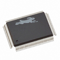
20-668-0003 Rabbit Semiconductor, 20-668-0003 Datasheet - Page 132

20-668-0003
Manufacturer Part Number
20-668-0003
Description
IC CPU RABBIT2000 30MHZ 100PQFP
Manufacturer
Rabbit Semiconductor
Datasheet
1.20-668-0003.pdf
(228 pages)
Specifications of 20-668-0003
Processor Type
Rabbit 2000 8-Bit
Speed
30MHz
Voltage
2.7V, 3V, 3.3V, 5V
Mounting Type
Surface Mount
Package / Case
100-MQFP, 100-PQFP
Data Bus Width
8 bit
Maximum Clock Frequency
30 MHz
Operating Supply Voltage
0 V to 5.5 V
Maximum Operating Temperature
+ 85 C
Mounting Style
SMD/SMT
Minimum Operating Temperature
- 40 C
Number Of Programmable I/os
40
Number Of Timers
8 & 10 bit
Lead Free Status / RoHS Status
Lead free / RoHS Compliant
Features
-
Lead Free Status / Rohs Status
Lead free / RoHS Compliant
Other names
20-668-0003
316-1062
316-1062
Available stocks
Company
Part Number
Manufacturer
Quantity
Price
Company:
Part Number:
20-668-0003
Manufacturer:
Rabbit Semiconductor
Quantity:
10 000
- Current page: 132 of 228
- Download datasheet (2Mb)
Table 12-4 lists the synchronous serial port signals.
To enable the clocked serial mode, a code must be in bits (3,2) of the control register,
enabling the clocked serial mode with either an internal clock or an external clock. The
transition between the external and the internal clock should be performed with care. Nor-
mally a pullup resistor is needed on the clock line to prevent spurious clocks while neither
party is driving the clock.
In clocked serial mode the shift register and the data register work in the same fashion as
for asynchronous communications. However, to initiate sending or receiving, a code must
be stored in bits (7,6) of the control register for each byte sent or received. One code spec-
ifies sending a byte, a different code specifies receiving a byte. The effect of these codes is
different, depending on whether the mode is internal clock or external clock.
To transmit in internal clock mode, the user must first load the data register (which must
be empty) and then store the send code. When the shift register finishes sending the cur-
rent character, if any, the data register will be loaded into the shift register and transmitted
by an 8-clock burst. One character can be in the process of transmitting while another
character is waiting in the data register tagged with the send code. The send code is effec-
tively double-buffered.
To receive a character in internal clock mode, the receive shift register should be idle. The
user then stores the receive code in the control register. A burst of 8 clocks will be gener-
ated and the sender must detect the clocks and shift output data to the data line on the fall-
ing edge of each clock. The receiver will sample the data on the rising edge of each clock.
The receive mode cannot double-buffer characters when using the internal clock. The shift
register must be idle before another character receive can be initiated. However, the inter-
rupt request and character ready takes place on the rising edge of the last clock pulse. If
the next receive code is stored before the natural location of the next falling edge, another
receive will be initiated without pausing the clock. To do this, the interrupt has to be ser-
viced within 1/2 clock.
To transmit each byte in external clock mode, the user must load the data register and then
store the send code. When the shift register is idle and the receiver provides a clock burst,
the data bits are transferred to the shift register and are shifted out. Once the transfer is
126
CLKA or CLKB
TxA or TxB on Parallel Port
CATxA or ATxB on Parallel Port D
RxA or RxB on Parallel Port C
ARxA or ARxB on Parallel Port D
Table 12-4. Synchronous Serial Port Signals
Signal Names
Rabbit
Serial Clock
Data Transmit
Data Receive
Rabbit 2000 Microprocessor User’s Manual
Pin Function
Related parts for 20-668-0003
Image
Part Number
Description
Manufacturer
Datasheet
Request
R

Part Number:
Description:
IC CPU RABBIT4000 128-LQFP
Manufacturer:
Rabbit Semiconductor
Datasheet:

Part Number:
Description:
IC MPU RABIT3000A 55.5MHZ128LQFP
Manufacturer:
Rabbit Semiconductor
Datasheet:

Part Number:
Description:
Microprocessors - MPU Rabbit 3000 TFBGA Microprocessor
Manufacturer:
Rabbit Semiconductor

Part Number:
Description:
Microprocessors - MPU Rabbit 4000 LQFP Microprocessor
Manufacturer:
Rabbit Semiconductor

Part Number:
Description:
IC, I/O EXPANDER, 8BIT, 40MHZ, TQFP-64
Manufacturer:
Rabbit Semiconductor

Part Number:
Description:
SCRs 1.5A 200uA 400V Sensing
Manufacturer:
Littelfuse Inc
Datasheet:

Part Number:
Description:
CARD 6-RELAY SMARTSTAR SR9500
Manufacturer:
Rabbit Semiconductor
Datasheet:

Part Number:
Description:
WIRE-BOARD CONN RECEPTACLE, 6POS, 3.96MM
Manufacturer:
TE Connectivity
Datasheet:

Part Number:
Description:
ADAPTER 20 PIN .420" PLUGS(6PCS)
Manufacturer:
Logical Systems Inc.
Datasheet:

Part Number:
Description:
CONN BARRIER BLOCK .438" 20 POS
Manufacturer:
Cinch Connectors
Datasheet:

Part Number:
Description:
20 MODII 2PC HDR DR SHRD, ROHS
Manufacturer:
TE Connectivity
Datasheet:

Part Number:
Description:
WIRE-BOARD CONN RECEPTACLE, 6POS, 3.96MM
Manufacturer:
TE Connectivity
Datasheet:


