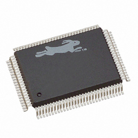
20-668-0003 Rabbit Semiconductor, 20-668-0003 Datasheet - Page 221

20-668-0003
Manufacturer Part Number
20-668-0003
Description
IC CPU RABBIT2000 30MHZ 100PQFP
Manufacturer
Rabbit Semiconductor
Datasheet
1.20-668-0003.pdf
(228 pages)
Specifications of 20-668-0003
Processor Type
Rabbit 2000 8-Bit
Speed
30MHz
Voltage
2.7V, 3V, 3.3V, 5V
Mounting Type
Surface Mount
Package / Case
100-MQFP, 100-PQFP
Data Bus Width
8 bit
Maximum Clock Frequency
30 MHz
Operating Supply Voltage
0 V to 5.5 V
Maximum Operating Temperature
+ 85 C
Mounting Style
SMD/SMT
Minimum Operating Temperature
- 40 C
Number Of Programmable I/os
40
Number Of Timers
8 & 10 bit
Lead Free Status / RoHS Status
Lead free / RoHS Compliant
Features
-
Lead Free Status / Rohs Status
Lead free / RoHS Compliant
Other names
20-668-0003
316-1062
316-1062
Available stocks
Company
Part Number
Manufacturer
Quantity
Price
Company:
Part Number:
20-668-0003
Manufacturer:
Rabbit Semiconductor
Quantity:
10 000
- Current page: 221 of 228
- Download datasheet (2Mb)
B.2.12 Clock Spectrum Spreader Module
This is a feature introduced on the Rabbit 3000 and migrated to revisions B and C of the
Rabbit 2000. The clock spectrum spreader and early memory output enable are turned on
by default for the Rabbit 2000C in Dynamic C version 7.32 and higher. The spectrum
spreader is very powerful for reducing EMI because it will reduce all sources of EMI
above 100 MHz that are related to the clock by about 15 dB. This is a very large reduction
since it is common to struggle to reduce EMI by 5 dB in order to pass government tests.
The spectrum spreader modulates the clock so as to spread out the spectrum of the clock
and its harmonics. Since the government tests use a 120 kHz bandwidth to measure EMI,
spreading the energy of a given harmonic over a wider bandwidth will decrease the
amount of EMI measured for a given harmonic. The spectrum spreader not only reduces
the EMI measured in government tests, but it will also often reduce the interference cre-
ated for radio and television reception.
The spectrum spreader has three settings under software control: off, normal spreading,
and strong spreading.
Two registers control the clock spectrum spreader. These registers must be loaded in a spe-
cific manner with proper time delays. GCM0R is only read by the spectrum spreader at the
moment when the spectrum spreader is enabled by storing 0x080 in GCM1R. If GCM1R
is cleared (when disabling the spectrum spreader), there is up to a 500-clock delay before
the spectrum spreader is actually disabled. The proper procedure is to clear GCM1R, wait
for 500 clocks, set GCM0R, and then enable the spreader by storing 0x080 in GCM1R.
Appendix B Rabbit 2000 Revisions
Figure B-2. Peak Spectral Amplitude Reduction from Spectrum Spreader
15 dB
10
5
50
Normal Spreading
100
Strong Spreading
150
MHz
200
250
300
350
215
Related parts for 20-668-0003
Image
Part Number
Description
Manufacturer
Datasheet
Request
R

Part Number:
Description:
IC CPU RABBIT4000 128-LQFP
Manufacturer:
Rabbit Semiconductor
Datasheet:

Part Number:
Description:
IC MPU RABIT3000A 55.5MHZ128LQFP
Manufacturer:
Rabbit Semiconductor
Datasheet:

Part Number:
Description:
Microprocessors - MPU Rabbit 3000 TFBGA Microprocessor
Manufacturer:
Rabbit Semiconductor

Part Number:
Description:
Microprocessors - MPU Rabbit 4000 LQFP Microprocessor
Manufacturer:
Rabbit Semiconductor

Part Number:
Description:
IC, I/O EXPANDER, 8BIT, 40MHZ, TQFP-64
Manufacturer:
Rabbit Semiconductor

Part Number:
Description:
SCRs 1.5A 200uA 400V Sensing
Manufacturer:
Littelfuse Inc
Datasheet:

Part Number:
Description:
CARD 6-RELAY SMARTSTAR SR9500
Manufacturer:
Rabbit Semiconductor
Datasheet:

Part Number:
Description:
WIRE-BOARD CONN RECEPTACLE, 6POS, 3.96MM
Manufacturer:
TE Connectivity
Datasheet:

Part Number:
Description:
ADAPTER 20 PIN .420" PLUGS(6PCS)
Manufacturer:
Logical Systems Inc.
Datasheet:

Part Number:
Description:
CONN BARRIER BLOCK .438" 20 POS
Manufacturer:
Cinch Connectors
Datasheet:

Part Number:
Description:
20 MODII 2PC HDR DR SHRD, ROHS
Manufacturer:
TE Connectivity
Datasheet:

Part Number:
Description:
WIRE-BOARD CONN RECEPTACLE, 6POS, 3.96MM
Manufacturer:
TE Connectivity
Datasheet:


