MC68332GCEH20 Freescale Semiconductor, MC68332GCEH20 Datasheet - Page 179
MC68332GCEH20
Manufacturer Part Number
MC68332GCEH20
Description
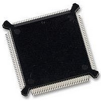
IC MCU 32BIT 20MHZ 132-PQFP
Manufacturer
Freescale Semiconductor
Series
M683xxr
Specifications of MC68332GCEH20
Core Processor
CPU32
Core Size
32-Bit
Speed
20MHz
Connectivity
EBI/EMI, SCI, SPI, UART/USART
Peripherals
POR, PWM, WDT
Number Of I /o
15
Program Memory Type
ROMless
Ram Size
2K x 8
Voltage - Supply (vcc/vdd)
4.5 V ~ 5.5 V
Oscillator Type
Internal
Operating Temperature
-40°C ~ 85°C
Package / Case
132-QFP
Controller Family/series
68K
No. Of I/o's
15
Ram Memory Size
2KB
Cpu Speed
20MHz
No. Of Timers
1
Embedded Interface Type
QSPI, SCI, UART
Digital Ic Case Style
PQFP
Rohs Compliant
Yes
Data Bus Width
32 bit
Data Ram Size
2 KB
Interface Type
QSPI, SCI, UART
Maximum Clock Frequency
20 MHz
Number Of Programmable I/os
15
Number Of Timers
16
Maximum Operating Temperature
+ 85 C
Mounting Style
SMD/SMT
Minimum Operating Temperature
- 40 C
Lead Free Status / RoHS Status
Lead free / RoHS Compliant
Eeprom Size
-
Program Memory Size
-
Data Converters
-
Lead Free Status / Rohs Status
Details
Available stocks
Company
Part Number
Manufacturer
Quantity
Price
Company:

Part Number:
MC68332GCEH20
Manufacturer:
Freescale Semiconductor
Quantity:
10 000
Part Number:
MC68332GCEH20
Manufacturer:
FREESCALE
Quantity:
20 000


MC68332
USER’S MANUAL
Notes For Tables 4 And 4a:
1. All internal registers retain data at 0 Hz.
2. This parameter is periodically sampled rather than 100% tested.
3. Assumes that a low-leakage external filter network is used to condition clock synthesizer input voltage. Total
4. Proper layout procedures must be followed to achieve specifications.
5. Assumes that stable V
6. Internal VCO frequency (f
7. Stability is the average deviation from the programmed frequency measured over the specified interval at max-
external resistance from the XFC pin due to external leakage must be greater than 15 M
specification. Filter network geometry can vary depending upon operating environment (See 4.3 System
Clock).
time V
for PLL lock after changing the W and Y frequency control bits in the synthesizer control register (SYNCR) while
the PLL is running, and to the period required for the clock to lock after LPSTOP.
by-two circuit that is not in the synthesizer feedback loop. When X = 0, the divider is enabled, and f
specified f
imum f
ternal clock signal. Noise injected into the PLL circuitry via V
frequency increase the C
trol system operation, this parameter should be measured during functional testing of the final system.
Num
4. When X = 1, the divider is disabled, and f
1
2
3
4
5
6
DD
sys
. Measurements are made with the device powered by filtered supplies and clocked by a stable ex-
and V
sys
Limp Mode Clock Frequency
CLKOUT Stability
PLL Reference Frequency Range
System Frequency
On-Chip PLL System Frequency
External Clock Operation
PLL Lock Time
VCO Frequency
.
SYNCR X bit = 0
SYNCR X bit = 1
Short term (5 s interval)
Long term (500 s interval)
DDSYN
Table A-4a. 20.97 MHz Clock Control Timing
(V
DD
DDSYN
are valid until RESET is released. This specification also applies to the period required
Freescale Semiconductor, Inc.
stab
Characteristic
and V
VCO
For More Information On This Product,
2,3,4,5
6
percentage for a given interval. When clock stability is a critical constraint on con-
is applied, and that the crystal oscillator is stable. Lock time is measured from the
) is determined by SYNCR W and Y bit values. The SYNCR X bit controls a divide-
2,3,4,7
ELECTRICAL CHARACTERISTICS
1
DDSYN
Go to: www.freescale.com
= 5.0 Vdc 5%, V
32.768 kHz reference
sys
= f
VCO
SS
Symbol
C
f
f
f
VCO
f
t
limp
= 0 Vdc, T
sys
stab
)
ref
lpll
2. X must equal one when operating at maximum
DDSYN
and V
A
= T
0.131
–0.05
–0.5
Min
25
dc
dc
—
—
—
—
L
SS
to T
and variation in crystal oscillator
H,
2 (f
f
sys
f
sys
20.97
20.97
20.97
sys
Max
0.05
0.5
50
20
max/2
max
max)
to guarantee this
MHz
MHz
MHz
Unit
kHz
ms
sys
= f
VCO
A-5
Related parts for MC68332GCEH20
Image
Part Number
Description
Manufacturer
Datasheet
Request
R

Part Number:
Description:
Manufacturer:
Freescale Semiconductor, Inc
Datasheet:
Part Number:
Description:
Manufacturer:
Freescale Semiconductor, Inc
Datasheet:
Part Number:
Description:
Manufacturer:
Freescale Semiconductor, Inc
Datasheet:
Part Number:
Description:
Manufacturer:
Freescale Semiconductor, Inc
Datasheet:
Part Number:
Description:
Manufacturer:
Freescale Semiconductor, Inc
Datasheet:
Part Number:
Description:
Manufacturer:
Freescale Semiconductor, Inc
Datasheet:
Part Number:
Description:
Manufacturer:
Freescale Semiconductor, Inc
Datasheet:
Part Number:
Description:
Manufacturer:
Freescale Semiconductor, Inc
Datasheet:
Part Number:
Description:
Manufacturer:
Freescale Semiconductor, Inc
Datasheet:
Part Number:
Description:
Manufacturer:
Freescale Semiconductor, Inc
Datasheet:
Part Number:
Description:
Manufacturer:
Freescale Semiconductor, Inc
Datasheet:
Part Number:
Description:
Manufacturer:
Freescale Semiconductor, Inc
Datasheet:
Part Number:
Description:
Manufacturer:
Freescale Semiconductor, Inc
Datasheet:
Part Number:
Description:
Manufacturer:
Freescale Semiconductor, Inc
Datasheet:
Part Number:
Description:
Manufacturer:
Freescale Semiconductor, Inc
Datasheet: