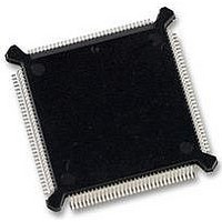
MC68332GCEH20 Freescale Semiconductor, MC68332GCEH20 Datasheet - Page 85

MC68332GCEH20
Manufacturer Part Number
MC68332GCEH20
Description
IC MCU 32BIT 20MHZ 132-PQFP
Manufacturer
Freescale Semiconductor
Series
M683xxr
Specifications of MC68332GCEH20
Core Processor
CPU32
Core Size
32-Bit
Speed
20MHz
Connectivity
EBI/EMI, SCI, SPI, UART/USART
Peripherals
POR, PWM, WDT
Number Of I /o
15
Program Memory Type
ROMless
Ram Size
2K x 8
Voltage - Supply (vcc/vdd)
4.5 V ~ 5.5 V
Oscillator Type
Internal
Operating Temperature
-40°C ~ 85°C
Package / Case
132-QFP
Controller Family/series
68K
No. Of I/o's
15
Ram Memory Size
2KB
Cpu Speed
20MHz
No. Of Timers
1
Embedded Interface Type
QSPI, SCI, UART
Digital Ic Case Style
PQFP
Rohs Compliant
Yes
Data Bus Width
32 bit
Data Ram Size
2 KB
Interface Type
QSPI, SCI, UART
Maximum Clock Frequency
20 MHz
Number Of Programmable I/os
15
Number Of Timers
16
Maximum Operating Temperature
+ 85 C
Mounting Style
SMD/SMT
Minimum Operating Temperature
- 40 C
Lead Free Status / RoHS Status
Lead free / RoHS Compliant
Eeprom Size
-
Program Memory Size
-
Data Converters
-
Lead Free Status / Rohs Status
Details
Available stocks
Company
Part Number
Manufacturer
Quantity
Price
Company:
Part Number:
MC68332GCEH20
Manufacturer:
Freescale Semiconductor
Quantity:
10 000
Part Number:
MC68332GCEH20
Manufacturer:
FREESCALE
Quantity:
20 000
- Current page: 85 of 265
- Download datasheet (7Mb)
CLKOUT
CYCLES
4.6.8 Reset Processing Summary
MC68332
USER’S MANUAL
RESET
NOTES:
LOCK
VCO
1. Internal start-up time.
2. SSP fetched.
3. PC fetched.
4. First instruction fetched.
V DD
BUS
To prevent write cycles in progress from being corrupted, a reset is recognized at the
end of a bus cycle, and not at an instruction boundary. Any processing in progress at
the time a reset occurs is aborted. After SIM reset control logic has synchronized an
internal or external reset request, it asserts the MSTRST signal.
The following events take place when MSTRST is asserted.
The following events take place when MSTRST is negated after assertion.
A. Instruction execution is aborted.
B. The status register is initialized.
C. The vector base register is initialized to $000000.
A. The CPU32 samples the BKPT input.
B. The CPU32 fetches the reset vector:
C. The CPU32 fetches and begins decoding the first instruction to be executed.
BUS STATE
UNKNOWN
Vectors can be fetched from internal RAM or from external ROM enabled by the
CSBOOT signal.
1. The T0 and T1 bits are cleared to disable tracing.
2. The S bit is set to establish supervisor privilege level.
3. The interrupt priority mask is set to $7, disabling all interrupts below priority
1. The first long word of the vector is loaded into the interrupt stack pointer.
2. The second long word of the vector is loaded into the program counter.
7.
Freescale Semiconductor, Inc.
CONTROL SIGNALS
For More Information On This Product,
THREE-STATED
ADDRESS AND
Figure 4-16 Power-On Reset
SYSTEM INTEGRATION MODULE
512 CLOCKS
Go to: www.freescale.com
10 CLOCKS
1
2
3
32 POR TIM
4-45
4
Related parts for MC68332GCEH20
Image
Part Number
Description
Manufacturer
Datasheet
Request
R
Part Number:
Description:
Manufacturer:
Freescale Semiconductor, Inc
Datasheet:
Part Number:
Description:
Manufacturer:
Freescale Semiconductor, Inc
Datasheet:
Part Number:
Description:
Manufacturer:
Freescale Semiconductor, Inc
Datasheet:
Part Number:
Description:
Manufacturer:
Freescale Semiconductor, Inc
Datasheet:
Part Number:
Description:
Manufacturer:
Freescale Semiconductor, Inc
Datasheet:
Part Number:
Description:
Manufacturer:
Freescale Semiconductor, Inc
Datasheet:
Part Number:
Description:
Manufacturer:
Freescale Semiconductor, Inc
Datasheet:
Part Number:
Description:
Manufacturer:
Freescale Semiconductor, Inc
Datasheet:
Part Number:
Description:
Manufacturer:
Freescale Semiconductor, Inc
Datasheet:
Part Number:
Description:
Manufacturer:
Freescale Semiconductor, Inc
Datasheet:
Part Number:
Description:
Manufacturer:
Freescale Semiconductor, Inc
Datasheet:
Part Number:
Description:
Manufacturer:
Freescale Semiconductor, Inc
Datasheet:
Part Number:
Description:
Manufacturer:
Freescale Semiconductor, Inc
Datasheet:
Part Number:
Description:
Manufacturer:
Freescale Semiconductor, Inc
Datasheet:
Part Number:
Description:
Manufacturer:
Freescale Semiconductor, Inc
Datasheet:


