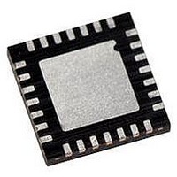
PIC16LF723A-I/ML Microchip Technology, PIC16LF723A-I/ML Datasheet - Page 119

PIC16LF723A-I/ML
Manufacturer Part Number
PIC16LF723A-I/ML
Description
MCU PIC 3.5K FLASH XLP 28-QFN
Manufacturer
Microchip Technology
Series
PIC® XLP™ 16Fr
Specifications of PIC16LF723A-I/ML
Core Size
8-Bit
Program Memory Size
7KB (4K x 14)
Peripherals
Brown-out Detect/Reset, POR, PWM, WDT
Core Processor
PIC
Speed
20MHz
Connectivity
I²C, SPI, UART/USART
Number Of I /o
25
Program Memory Type
FLASH
Ram Size
192 x 8
Voltage - Supply (vcc/vdd)
1.8 V ~ 3.6 V
Data Converters
A/D 11x8b
Oscillator Type
Internal
Operating Temperature
-40°C ~ 85°C
Package / Case
28-VQFN Exposed Pad, 28-HVQFN, 28-SQFN, 28-DHVQFN
Controller Family/series
PIC16LF
No. Of I/o's
25
Ram Memory Size
192Byte
Cpu Speed
20MHz
No. Of Timers
3
Lead Free Status / RoHS Status
Lead free / RoHS Compliant
Eeprom Size
-
Lead Free Status / RoHS Status
Lead free / RoHS Compliant, Lead free / RoHS Compliant
- Current page: 119 of 284
- Download datasheet (3Mb)
14.5
The software portion of the capacitive sensing module
is required to determine the change in frequency of the
capacitive sensing oscillator. This is accomplished by
the following:
• Setting a fixed time base to acquire counts on
• Establishing the nominal frequency for the
• Establishing the reduced frequency for the
• Set the frequency threshold
14.5.1
To determine the nominal frequency of the capacitive
sensing oscillator:
• Remove any extra capacitive load on the selected
• At the start of the fixed time base, clear the timer
• At the end of the fixed time base save the value in
The value of the timer resource is the number of
oscillations of the capacitive sensing oscillator for the
given time base. The frequency of the capacitive
sensing oscillator is equal to the number of counts on
in the timer divided by the period of the fixed time base.
14.5.2
The extra capacitive load will cause the frequency of the
capacitive sensing oscillator to decrease. To determine
the reduced frequency of the capacitive sensing
oscillator:
• Add a typical capacitive load on the selected
• Use the same fixed time base as the nominal
• At the start of the fixed time base, clear the timer
• At the end of the fixed time base save the value in
The value of the timer resource is the number of oscil-
lations of the capacitive sensing oscillator with an addi-
tional capacitive load. The frequency of the capacitive
sensing oscillator is equal to the number of counts on
in the timer divided by the period of the fixed time base.
This frequency should be less than the value obtained
during the nominal frequency measurement.
2010 Microchip Technology Inc.
Timer0 or Timer1
capacitive sensing oscillator
capacitive sensing oscillator due to an additional
capacitive load
CPSx pin
resource
the timer resource
CPSx pin
frequency measurement
resource
the timer resource
Software Control
NOMINAL FREQUENCY
(NO CAPACITIVE LOAD)
REDUCED FREQUENCY
(ADDITIONAL CAPACITIVE LOAD)
PIC16F/LF722A/723A
14.5.3
The frequency threshold should be placed midway
between the value of nominal frequency and the
reduced frequency of the capacitive sensing oscillator.
Refer to Application Note AN1103, “Software Handling
for Capacitive Sensing” (DS01103) for more detailed
information the software required for capacitive
sensing module.
Note:
•AN1101, “Introduction to Capacitive
•AN1102, “Layout and Physical Design
FREQUENCY THRESHOLD
For more information on general capacitive
sensing refer to Application Notes:
Sensing” (DS01101)
Guidelines for Capacitive Sensing”
(DS01102)
DS41417A-page 119
Related parts for PIC16LF723A-I/ML
Image
Part Number
Description
Manufacturer
Datasheet
Request
R

Part Number:
Description:
IC PIC MCU FLASH 8KX14 28-SPDIP
Manufacturer:
Microchip Technology
Datasheet:

Part Number:
Description:
IC PIC MCU FLASH 8KX14 28-QFN
Manufacturer:
Microchip Technology
Datasheet:

Part Number:
Description:
IC PIC MCU FLASH 8KX14 28-SPDIP
Manufacturer:
Microchip Technology
Datasheet:

Part Number:
Description:
IC PIC MCU FLASH 8KX14 28-QFN
Manufacturer:
Microchip Technology
Datasheet:

Part Number:
Description:
IC PIC MCU FLASH 8KX14 28-SOIC
Manufacturer:
Microchip Technology
Datasheet:

Part Number:
Description:
IC PIC MCU FLASH 8KX14 28-SSOP
Manufacturer:
Microchip Technology
Datasheet:

Part Number:
Description:
IC PIC MCU FLASH 8KX14 28-SSOP
Manufacturer:
Microchip Technology
Datasheet:

Part Number:
Description:
7 KB Flash, 16 MHz Int. Osc, NanoWatt XLP 28 SOIC .300in TUBE
Manufacturer:
Microchip Technology
Datasheet:

Part Number:
Description:
IC PIC MCU FLASH 2KX14 28SOIC
Manufacturer:
Microchip Technology
Datasheet:

Part Number:
Description:
IC PIC MCU FLASH 2KX14 28QFN
Manufacturer:
Microchip Technology
Datasheet:

Part Number:
Description:
IC PIC MCU FLASH 2KX14 28DIP
Manufacturer:
Microchip Technology
Datasheet:

Part Number:
Description:
IC MCU FLASH 2KX14 28SOIC
Manufacturer:
Microchip Technology

Part Number:
Description:
IC PIC MCU FLASH 2KX14 28QFN
Manufacturer:
Microchip Technology

Part Number:
Description:
IC PIC MCU FLASH 2KX14 28SSOP
Manufacturer:
Microchip Technology
Datasheet:

Part Number:
Description:
IC, 8BIT MCU, PIC16LF, 32MHZ, QFN-28
Manufacturer:
Microchip Technology
Datasheet:


