M38039FFHFP#U0 Renesas Electronics America, M38039FFHFP#U0 Datasheet - Page 114
M38039FFHFP#U0
Manufacturer Part Number
M38039FFHFP#U0
Description
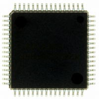
IC 740 MCU FLASH 60K 64QFP
Manufacturer
Renesas Electronics America
Series
740/38000r
Datasheet
1.M38039FFHFPU0.pdf
(119 pages)
Specifications of M38039FFHFP#U0
Core Processor
740
Core Size
8-Bit
Speed
16.8MHz
Connectivity
SIO, UART/USART
Peripherals
PWM, WDT
Number Of I /o
56
Program Memory Size
60KB (60K x 8)
Program Memory Type
FLASH
Ram Size
2K x 8
Voltage - Supply (vcc/vdd)
2.7 V ~ 5.5 V
Data Converters
A/D 16x10b; D/A 2x8b
Oscillator Type
Internal
Operating Temperature
-20°C ~ 85°C
Package / Case
64-QFP
Lead Free Status / RoHS Status
Lead free / RoHS Compliant
Eeprom Size
-
Available stocks
Company
Part Number
Manufacturer
Quantity
Price


3803 Group (Spec.H)
Rev.3.11
REJ03B0017-0311
Notes on Restarting Oscillation
• Restarting oscillation
Usually, when the MCU stops the clock oscillation by STP
instruction and the STP instruction has been released by an
external interrupt source, the fixed values of Timer 1 and
Prescaler 12 (Timer 1 = “01
automatically reloaded in order for the oscillation to stabilize.
The user can inhibit the automatic setting by writing “1” to bit 0
of MISRG (address 0010
However, by setting this bit to “1”, the previous values, set just
before the STP instruction was executed, will remain in Timer 1
and Prescaler 12. Therefore, you will need to set an appropriate
value to each register, in accordance with the oscillation
stabilizing time, before executing the STP instruction.
<Reason>
Oscillation will restart when an external interrupt is received.
However, internal clock
Timer 1 starts to underflow. This ensures time for the clock
oscillation using the ceramic resonators to be stabilized.
Notes on Using Stop Mode
• Register setting
Since values of the prescaler 12 and Timer 1 are automatically
reloaded when returning from the stop mode, set them again,
respectively. (When the oscillation stabilizing time set after STP
instruction released bit is “0”)
• Clock restoration
After restoration from the stop mode to the normal mode by an
interrupt request, the contents of the CPU mode register previous
to the STP instruction execution are retained. Accordingly, if
both main clock and sub clock were oscillating before execution
of the STP instruction, the oscillation of both clocks is resumed
at restoration.
In the above case, when the main clock side is set as a system
clock, the oscillation stabilizing time for approximately 8,000
cycles of the X
mode. At this time, note that the oscillation on the sub clock side
may not be stabilized even after the lapse of the oscillation
stabilizing time of the main clock side.
Notes on Wait Mode
• Clock restoration
If the wait mode is released by a reset when X
system clock and X
the WIT instruction, X
starts, and X
In the above case, the RESET pin should be held at “L” until the
oscillation is stabilized.
Notes on CPU rewrite mode of flash memory version
1. Operation speed
During CPU rewrite mode, set the system clock
less using the main clock division ratio selection bits (bits 6 and
7 of address 003B
2. Instructions inhibited against use
The instructions which refer to the internal data of the flash
memory cannot be used during the CPU rewrite mode.
3. Interrupts inhibited against use
The interrupts cannot be used during the CPU rewrite mode
because they refer to the internal data of the flash memory.
IN
Apr 5, 2006
is set as the system clock.
IN
16
input is reserved at restoration from the stop
IN
).
oscillation is stopped during execution of
CIN
16
φ
).
is supplied to the CPU only when
oscillation stops, X
16
”, Prescaler 12 = “FF
Page 112 of 113
CIN
IN
φ
oscillations
is set as the
4.0 MHz or
16
”) are
4. Watchdog timer
In case of the watchdog timer has been running already, the
internal reset generated by watchdog timer underflow does not
happen, because of watchdog timer is always clearing during
program or erase operation.
5. Reset
Reset is always valid. In case of CNV
released, boot mode is active. So the program starts from the
address contained in address FFFC
area.
Notes on flash memory version
The CNV
Connect the CNV
pattern which is supplied to the V
In addition connecting an approximately 1 k to 5 kΩ. resistor in
series to the GND could improve noise immunity. In this case as
well as the above mention, connect the pin the shortest possible
to the GND pattern which is supplied to the V
microcomputer.
Note. When the boot mode or the standard serial I/O mode is used, a
Fig 92. Wiring for the CNV
Notes on electric characteristic differences between
mask ROM and flash nemory version MCUs
There are differences in electric characteristics, operation
margin, noise immunity, and noise radiation between Mask ROM
and Flash Memory version MCUs due to the difference in the
manufacturing processes, built-in ROM, and layout pattern etc.
When manufacturing an application system with the Flash
Memory version and then switching to use of the Mask ROM
version, please conduct evaluations equivalent to the system
evaluations conducted for the flash memory version.
DATA REQUIRED FOR MASK ORDERS
The following are necessary when ordering a mask ROM
production:
1. Mask ROM Confirmation Form*
2. Mark Specification Form*
3. Data to be written to ROM, in EPROM form (three identical
* For the mask ROM confirmation and the mark specifications,
refer to the “Renesas Technology Corp.” Homepage
(http://www.renesas.com/en/rom).
copies)
switch of the input level to the CNV
SS
Note 1: Shows the microcomputer’s pin.
pin determines the flash memory mode.
SS
CNV
/V
PP
V
SS
SS
pin the shortest possible to the GND
(1)
(1)
SS
SS
16
pin of the microcomputer.
and FFFD
Approx. 5kΩ
SS
The shortest
The shortest
SS
pin is required.
= “H” when reset is
16
in boot ROM
SS
pin of the
Related parts for M38039FFHFP#U0
Image
Part Number
Description
Manufacturer
Datasheet
Request
R

Part Number:
Description:
KIT STARTER FOR M16C/29
Manufacturer:
Renesas Electronics America
Datasheet:

Part Number:
Description:
KIT STARTER FOR R8C/2D
Manufacturer:
Renesas Electronics America
Datasheet:

Part Number:
Description:
R0K33062P STARTER KIT
Manufacturer:
Renesas Electronics America
Datasheet:

Part Number:
Description:
KIT STARTER FOR R8C/23 E8A
Manufacturer:
Renesas Electronics America
Datasheet:

Part Number:
Description:
KIT STARTER FOR R8C/25
Manufacturer:
Renesas Electronics America
Datasheet:

Part Number:
Description:
KIT STARTER H8S2456 SHARPE DSPLY
Manufacturer:
Renesas Electronics America
Datasheet:

Part Number:
Description:
KIT STARTER FOR R8C38C
Manufacturer:
Renesas Electronics America
Datasheet:

Part Number:
Description:
KIT STARTER FOR R8C35C
Manufacturer:
Renesas Electronics America
Datasheet:

Part Number:
Description:
KIT STARTER FOR R8CL3AC+LCD APPS
Manufacturer:
Renesas Electronics America
Datasheet:
Part Number:
Description:
KIT STARTER FOR RX610
Manufacturer:
Renesas Electronics America
Datasheet:

Part Number:
Description:
KIT STARTER FOR R32C/118
Manufacturer:
Renesas Electronics America
Datasheet:

Part Number:
Description:
KIT DEV RSK-R8C/26-29
Manufacturer:
Renesas Electronics America
Datasheet:

Part Number:
Description:
KIT STARTER FOR SH7124
Manufacturer:
Renesas Electronics America
Datasheet:

Part Number:
Description:
KIT STARTER FOR H8SX/1622
Manufacturer:
Renesas Electronics America
Datasheet:

Part Number:
Description:
KIT DEV FOR SH7203
Manufacturer:
Renesas Electronics America
Datasheet: