M38039FFHFP#U0 Renesas Electronics America, M38039FFHFP#U0 Datasheet - Page 99
M38039FFHFP#U0
Manufacturer Part Number
M38039FFHFP#U0
Description
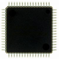
IC 740 MCU FLASH 60K 64QFP
Manufacturer
Renesas Electronics America
Series
740/38000r
Datasheet
1.M38039FFHFPU0.pdf
(119 pages)
Specifications of M38039FFHFP#U0
Core Processor
740
Core Size
8-Bit
Speed
16.8MHz
Connectivity
SIO, UART/USART
Peripherals
PWM, WDT
Number Of I /o
56
Program Memory Size
60KB (60K x 8)
Program Memory Type
FLASH
Ram Size
2K x 8
Voltage - Supply (vcc/vdd)
2.7 V ~ 5.5 V
Data Converters
A/D 16x10b; D/A 2x8b
Oscillator Type
Internal
Operating Temperature
-20°C ~ 85°C
Package / Case
64-QFP
Lead Free Status / RoHS Status
Lead free / RoHS Compliant
Eeprom Size
-
Available stocks
Company
Part Number
Manufacturer
Quantity
Price


3803 Group (Spec.H)
Rev.3.11
REJ03B0017-0311
A/D converter characteristics
Table 27 A/D converter recommended operating conditions (Flash memory version)
NOTES:
Table 28 A/D converter characteristics (Flash memory version)
NOTES:
D/A converter characteristics
Table 29 D/A converter characteristics (Flash memory version)
NOTE:
Table 30 Power source circuit timing characteristics (Flash memory version)
V
V
AV
V
f(X
t
R
I
I
tsu
RO
I
CONV
VREF
I(AD)
VREF
Symbol
Symbol
CC
REF
IA
1. 8-bit A/D mode: When the conversion mode selection bit (bit 7 of address 0038
2. 10-bit A/D mode: When the conversion mode selection bit (bit 7 of address 0038
1. 8-bit A/D mode: When the conversion mode selection bit (bit 7 of address 0038
2. 10-bit A/D mode: When the conversion mode selection bit (bit 7 of address 0038
1. Using one D/A converter, with the value in the DA conversion register of the other D/A converter being “00
LADDER
SS
IN
td(P−R)
Symbol
Symbol
−
−
)
−
−
(V
(V
(V
(V
Power source voltage
(When A/D converter is used)
Analog convert reference voltage
Analog power source voltage
Analog input voltage AN
Main clock input oscillation
frequency
(When A/D converter is used)
Resolution
Absolute accuracy
(excluding quantization error)
Conversion time
Ladder resistor
Reference power
source input current
A/D port input current
Apr 5, 2006
CC
CC
CC
CC
Resolution
Absolute accuracy
Setting time
Output resistor
Reference power source input current
Internal power source stable time
at power-on
= 2.7 to 5.5 V, V
= 2.7 to 5.5 V, V
= 2.7 to 5.5 V, V
= 2.7 to 5.5 V, V
Parameter
Parameter
Parameter
at A/D converter operated V
at A/D converter stopped
Page 97 of 113
SS
SS
REF
REF
0
-AN
Parameter
= AV
= AV
= 2.7 V to V
= 2.7 V to V
15
SS
SS
4.0 ≤ V
2.7 ≤ V
= 0 V, Ta = –20 to 85 °C, unless otherwise noted)
= 0 V, Ta = –20 to 85 °C, unless otherwise noted)
2.7 ≤ V
4.5 ≤ V
8-bit A/D mode
10-bit A/D mode
4.0 ≤ V
REF
REF
2.7 ≤ V
CC
CC
Test conditions
(1)
CC
CC
CC
≤ 5.5 V
< 4.0 V
Conditions
, V
, V
= V
= V
= V
SS
SS
CC
8-bit A/D mode
10-bit A/D mode
8-bit A/D mode
10-bit A/D mode
8-bit A/D mode
10-bit A/D mode
V
REF
REF
REF
< 5.5 V
REF
REF
(1)
= AV
= AV
(2)
< 4.0 V
< 4.5 V
≤ 5.5 V
= 5.0 V
= 5.0 V
SS
SS
= 0 V, Ta = –20 to 85 °C, unless otherwise noted)
= 0 V, Ta = –20 to 85 °C, unless otherwise noted)
Test conditions
(1)
(1)
(1)
(2)
(2)
(2)
Min.
Min.
Min.
2.7
2.7
2.0
0.5
0.5
0.5
2
0
2.7 ≤ V
2.7 ≤ V
16
16
16
16
) is “1”.
) is “1”.
) is “0”.
) is “0”.
Typ.
REF
REF
5.0
5.0
0
Limits
Limits
≤ 5.5 V
≤ 5.5 V
Typ.
Typ.
3.5
Limits
(
---------------------------------------------------------------------
24.6
(
--------------------------------------------------------- -
9
×
Min.
×
12
50
V
V
CC
CC
Max.
16.8
V
V
–
Max.
Max.
5.5
5.5
3
1.0
2.5
3.2
Limits
CC
CC
–
3
0.3
16
Typ.
8
3
5
2
150
35
62.7
”.
)
×
)
1.05
×
Max.
100
200
1.05
5.0
5.0
10
±2
±4
50
61
8
Unit
Unit
mA
kΩ
ms
bit
µs
2tc(X
%
MHz
LSB
LSB
Unit
Unit
kΩ
µA
µA
µA
bit
V
V
V
V
IN
)
Related parts for M38039FFHFP#U0
Image
Part Number
Description
Manufacturer
Datasheet
Request
R

Part Number:
Description:
KIT STARTER FOR M16C/29
Manufacturer:
Renesas Electronics America
Datasheet:

Part Number:
Description:
KIT STARTER FOR R8C/2D
Manufacturer:
Renesas Electronics America
Datasheet:

Part Number:
Description:
R0K33062P STARTER KIT
Manufacturer:
Renesas Electronics America
Datasheet:

Part Number:
Description:
KIT STARTER FOR R8C/23 E8A
Manufacturer:
Renesas Electronics America
Datasheet:

Part Number:
Description:
KIT STARTER FOR R8C/25
Manufacturer:
Renesas Electronics America
Datasheet:

Part Number:
Description:
KIT STARTER H8S2456 SHARPE DSPLY
Manufacturer:
Renesas Electronics America
Datasheet:

Part Number:
Description:
KIT STARTER FOR R8C38C
Manufacturer:
Renesas Electronics America
Datasheet:

Part Number:
Description:
KIT STARTER FOR R8C35C
Manufacturer:
Renesas Electronics America
Datasheet:

Part Number:
Description:
KIT STARTER FOR R8CL3AC+LCD APPS
Manufacturer:
Renesas Electronics America
Datasheet:
Part Number:
Description:
KIT STARTER FOR RX610
Manufacturer:
Renesas Electronics America
Datasheet:

Part Number:
Description:
KIT STARTER FOR R32C/118
Manufacturer:
Renesas Electronics America
Datasheet:

Part Number:
Description:
KIT DEV RSK-R8C/26-29
Manufacturer:
Renesas Electronics America
Datasheet:

Part Number:
Description:
KIT STARTER FOR SH7124
Manufacturer:
Renesas Electronics America
Datasheet:

Part Number:
Description:
KIT STARTER FOR H8SX/1622
Manufacturer:
Renesas Electronics America
Datasheet:

Part Number:
Description:
KIT DEV FOR SH7203
Manufacturer:
Renesas Electronics America
Datasheet: