M38039FFHFP#U0 Renesas Electronics America, M38039FFHFP#U0 Datasheet - Page 66
M38039FFHFP#U0
Manufacturer Part Number
M38039FFHFP#U0
Description
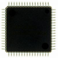
IC 740 MCU FLASH 60K 64QFP
Manufacturer
Renesas Electronics America
Series
740/38000r
Datasheet
1.M38039FFHFPU0.pdf
(119 pages)
Specifications of M38039FFHFP#U0
Core Processor
740
Core Size
8-Bit
Speed
16.8MHz
Connectivity
SIO, UART/USART
Peripherals
PWM, WDT
Number Of I /o
56
Program Memory Size
60KB (60K x 8)
Program Memory Type
FLASH
Ram Size
2K x 8
Voltage - Supply (vcc/vdd)
2.7 V ~ 5.5 V
Data Converters
A/D 16x10b; D/A 2x8b
Oscillator Type
Internal
Operating Temperature
-20°C ~ 85°C
Package / Case
64-QFP
Lead Free Status / RoHS Status
Lead free / RoHS Compliant
Eeprom Size
-
Available stocks
Company
Part Number
Manufacturer
Quantity
Price


3803 Group (Spec.H)
Rev.3.11
REJ03B0017-0311
CLOCK GENERATING CIRCUIT
The 3803 group (Spec.H) has two built-in oscillation circuits:
main clock X
X
connecting a resonator between X
X
resonator manufacturer’s recommended values. No external
resistor is needed between X
resistor exists on-chip.(An external feed-back resistor may be
needed depending on conditions.) However, an external feed-
back resistor is needed between X
Immediately after power on, only the X
starts oscillating, and X
• Frequency Control
(1) Middle-speed mode
The internal clock φ is the frequency of X
reset is released, this mode is selected.
(2) High-speed mode
The internal clock φ is half the frequency of X
(3) Low-speed mode
The internal clock φ is half the frequency of X
(4) Low power dissipation mode
The low power consumption operation can be realized by
stopping the main clock X
main clock, set bit 5 of the CPU mode register to “1”. When the
main clock X
“0”), set sufficient time for oscillation to stabilize.
The sub-clock X
input clocks that are generated externally. Accordingly, make
sure to cause an external resonator to oscillate.
COUT
COUT
oscillation circuit. An oscillation circuit can be formed by
). Use the circuit constants in accordance with the
IN
Apr 5, 2006
IN
-X
is restarted (by setting the main clock stop bit to
CIN
OUT
-X
CIN
COUT
oscillation circuit and sub clock X
and X
IN
oscillating circuit can not directly
in low-speed mode. To stop the
IN
COUT
Page 64 of 113
CIN
and X
and X
IN
pins function as I/O ports.
OUT
and X
IN
IN
COUT
divided by 8. After
oscillation circuit
since a feed-back
IN
CIN
OUT
.
.
.
(X
CIN
CIN
and
-
Oscillation Control
(1) Stop mode
If the STP instruction is executed, the internal clock φ stops at an
“H” level, and X
oscillation stabilizing time set after STP instruction released bit
(bit 0 of address 0010
and timer 1 is set to “01
set after STP instruction released bit is “1”, set the sufficient time
for oscillation of used oscillator to stabilize since nothing is set to
the prescaler 12 and timer 1.
After STP instruction is released, the input of the prescaler 12 is
connected to count source which had set at executing the STP
instruction, and the output of the prescaler 12 is connected to
timer 1. Oscillator restarts when an external interrupt is received,
but the internal clock φ is not supplied to the CPU (remains at
“H”) until timer 1 underflows. The internal clock φ is supplied
for the first time, when timer 1 underflows. This ensures time for
the clock oscillation using the ceramic resonators to be
stabilized. When the oscillator is restarted by reset, apply “L”
level to the RESET pin until the oscillation is stable since a wait
time will not be generated.
(2) Wait mode
If the WIT instruction is executed, the internal clock φ stops at an
“H” level, but the oscillator does not stop. The internal clock φ
restarts at reset or when an interrupt is received. Since the
oscillator does not stop, normal operation can be started
immediately after the clock is restarted.
To ensure that the interrupts will be received to release the STP
or WIT state, their interrupt enable bits must be set to “1” before
executing of the STP or WIT instruction.
When releasing the STP state, the prescaler 12 and timer 1 will
start counting the clock X
timer 1 interrupt enable bit to “0” before executing the STP
instruction.
<Notes>
• If you switch the mode between middle/high-speed and low-
• When using the quartz-crystal oscillator of high frequency,
• When using the oscillation stabilizing time set after STP
speed, stabilize both X
time is required for the sub clock to stabilize, especially
immediately after power on and at returning from stop mode.
When switching the mode between middle/high-speed and
low-speed, set the frequency on condition that f(X
3×f(X
such as 16 MHz etc., it may be necessary to select a specific
oscillator with the specification demanded.
instruction released bit set to “1”, evaluate time to stabilize
oscillation of the used oscillator and set the value to the timer 1
and prescaler 12.
CIN
).
IN
16
and X
16
) is “0”, the prescaler 12 is set to “FF
IN
”. When the oscillation stabilizing time
IN
and X
divided by 16. Accordingly, set the
CIN
CIN
oscillators stop. When the
oscillations. The sufficient
IN
) >
16
”
Related parts for M38039FFHFP#U0
Image
Part Number
Description
Manufacturer
Datasheet
Request
R

Part Number:
Description:
KIT STARTER FOR M16C/29
Manufacturer:
Renesas Electronics America
Datasheet:

Part Number:
Description:
KIT STARTER FOR R8C/2D
Manufacturer:
Renesas Electronics America
Datasheet:

Part Number:
Description:
R0K33062P STARTER KIT
Manufacturer:
Renesas Electronics America
Datasheet:

Part Number:
Description:
KIT STARTER FOR R8C/23 E8A
Manufacturer:
Renesas Electronics America
Datasheet:

Part Number:
Description:
KIT STARTER FOR R8C/25
Manufacturer:
Renesas Electronics America
Datasheet:

Part Number:
Description:
KIT STARTER H8S2456 SHARPE DSPLY
Manufacturer:
Renesas Electronics America
Datasheet:

Part Number:
Description:
KIT STARTER FOR R8C38C
Manufacturer:
Renesas Electronics America
Datasheet:

Part Number:
Description:
KIT STARTER FOR R8C35C
Manufacturer:
Renesas Electronics America
Datasheet:

Part Number:
Description:
KIT STARTER FOR R8CL3AC+LCD APPS
Manufacturer:
Renesas Electronics America
Datasheet:
Part Number:
Description:
KIT STARTER FOR RX610
Manufacturer:
Renesas Electronics America
Datasheet:

Part Number:
Description:
KIT STARTER FOR R32C/118
Manufacturer:
Renesas Electronics America
Datasheet:

Part Number:
Description:
KIT DEV RSK-R8C/26-29
Manufacturer:
Renesas Electronics America
Datasheet:

Part Number:
Description:
KIT STARTER FOR SH7124
Manufacturer:
Renesas Electronics America
Datasheet:

Part Number:
Description:
KIT STARTER FOR H8SX/1622
Manufacturer:
Renesas Electronics America
Datasheet:

Part Number:
Description:
KIT DEV FOR SH7203
Manufacturer:
Renesas Electronics America
Datasheet: