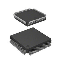
HD6413003TF16 Renesas Electronics America, HD6413003TF16 Datasheet - Page 77

HD6413003TF16
Manufacturer Part Number
HD6413003TF16
Description
IC H8 MCU ROMLESS QFP112
Manufacturer
Renesas Electronics America
Series
H8® H8/300Hr
Datasheet
1.D13003TF16V.pdf
(717 pages)
Specifications of HD6413003TF16
Core Processor
H8/300H
Core Size
16-Bit
Speed
16MHz
Connectivity
SCI
Peripherals
DMA, PWM, WDT
Number Of I /o
50
Program Memory Type
ROMless
Ram Size
512 x 8
Voltage - Supply (vcc/vdd)
2.7 V ~ 5.5 V
Data Converters
A/D 8x10b
Oscillator Type
Internal
Operating Temperature
-20°C ~ 75°C
Package / Case
112-QFP
Lead Free Status / RoHS Status
Contains lead / RoHS non-compliant
Eeprom Size
-
Program Memory Size
-
Available stocks
Company
Part Number
Manufacturer
Quantity
Price
Company:
Part Number:
HD6413003TF16
Manufacturer:
Renesas Electronics America
Quantity:
10 000
Company:
Part Number:
HD6413003TF16V
Manufacturer:
ITT
Quantity:
12 000
Company:
Part Number:
HD6413003TF16V
Manufacturer:
RENESAS
Quantity:
36
Part Number:
HD6413003TF16V
Manufacturer:
RENESAS/瑞萨
Quantity:
20 000
- Current page: 77 of 717
- Download datasheet (2Mb)
3.1 Overview
3.1.1 Operating Mode Selection
The H8/3003 has four operating modes (modes 1 to 4) that are selected by the mode pins (MD
MD
and the initial bus mode.
Table 3-1 Operating Mode Selection
Operating Mode
—
Mode 1
Mode 2
Mode 3
Mode 4
—
—
—
Notes: 1. In all modes, an 8-bit or 16-bit data bus can be selected on a per-area basis by settings
For the address space size there are two choices: 1 Mbyte or 16 Mbytes. The external data bus is
either 8 or 16 bits wide depending on the settings in the area bus width control register (ABWCR).
If 8-bit access is selected for all areas, the external data bus is 8 bits wide. For details see
section 6, Bus Controller.
Modes 1 to 4 are externally expanded modes that enable access to external memory and peripheral
devices. Modes 1 and 2 support a maximum address space of 1 Mbyte. Modes 3 and 4 support a
maximum address space of 16 Mbytes.
The H8/3003 can only be used in modes 1 to 4. The inputs at the mode pins must select one of
these four modes. The inputs at the mode pins must not be changed during operation.
0
) as indicated in table 3-1. The input at these pins determines the size of the address space
2. If the RAM enable bit (RAME) in the system control register (SYSCR) is cleared to 0,
made in the area bus width control register (ABWCR). For details see section 6, Bus
Controller.
these addresses become external addresses.
MD
0
0
0
0
1
1
1
1
Section 3 MCU Operating Modes
Mode Pins
2
MD
0
0
1
1
0
0
1
1
1
MD
0
1
0
1
0
1
0
1
0
Address Space
—
1 Mbyte
1 Mbyte
16 Mbytes
16 Mbytes
—
—
—
57
Initial Bus Mode
—
8 bits
16 bits
8 bits
16 bits
—
—
—
Description
*1
On-Chip RAM
—
Enabled
Enabled
Enabled
Enabled
—
—
—
*2
*2
*2
*2
2
to
Related parts for HD6413003TF16
Image
Part Number
Description
Manufacturer
Datasheet
Request
R

Part Number:
Description:
KIT STARTER FOR M16C/29
Manufacturer:
Renesas Electronics America
Datasheet:

Part Number:
Description:
KIT STARTER FOR R8C/2D
Manufacturer:
Renesas Electronics America
Datasheet:

Part Number:
Description:
R0K33062P STARTER KIT
Manufacturer:
Renesas Electronics America
Datasheet:

Part Number:
Description:
KIT STARTER FOR R8C/23 E8A
Manufacturer:
Renesas Electronics America
Datasheet:

Part Number:
Description:
KIT STARTER FOR R8C/25
Manufacturer:
Renesas Electronics America
Datasheet:

Part Number:
Description:
KIT STARTER H8S2456 SHARPE DSPLY
Manufacturer:
Renesas Electronics America
Datasheet:

Part Number:
Description:
KIT STARTER FOR R8C38C
Manufacturer:
Renesas Electronics America
Datasheet:

Part Number:
Description:
KIT STARTER FOR R8C35C
Manufacturer:
Renesas Electronics America
Datasheet:

Part Number:
Description:
KIT STARTER FOR R8CL3AC+LCD APPS
Manufacturer:
Renesas Electronics America
Datasheet:

Part Number:
Description:
KIT STARTER FOR RX610
Manufacturer:
Renesas Electronics America
Datasheet:

Part Number:
Description:
KIT STARTER FOR R32C/118
Manufacturer:
Renesas Electronics America
Datasheet:

Part Number:
Description:
KIT DEV RSK-R8C/26-29
Manufacturer:
Renesas Electronics America
Datasheet:

Part Number:
Description:
KIT STARTER FOR SH7124
Manufacturer:
Renesas Electronics America
Datasheet:

Part Number:
Description:
KIT STARTER FOR H8SX/1622
Manufacturer:
Renesas Electronics America
Datasheet:

Part Number:
Description:
KIT DEV FOR SH7203
Manufacturer:
Renesas Electronics America
Datasheet:


