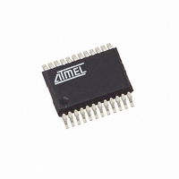
ATAM862P-TNSY4D Atmel, ATAM862P-TNSY4D Datasheet - Page 14

ATAM862P-TNSY4D
Manufacturer Part Number
ATAM862P-TNSY4D
Description
IC MCU FLASH 4K TX 433MHZ 24SSOP
Manufacturer
Atmel
Datasheet
1.ATAM862P-TNQY4D.pdf
(110 pages)
Specifications of ATAM862P-TNSY4D
Applications
UHF ASK/FSK
Core Processor
MARC4
Program Memory Type
FLASH (4 kB)
Controller Series
MARC4 4-Bit
Ram Size
256 x 4
Interface
SSI
Number Of I /o
11
Voltage - Supply
1.8 V ~ 4 V
Operating Temperature
-40°C ~ 125°C
Mounting Type
Surface Mount
Package / Case
24-SSOP
Processor Series
ATAM862x
Core
MARC4
Data Bus Width
4 bit
Mounting Style
SMD/SMT
Lead Free Status / RoHS Status
Lead free / RoHS Compliant
- Current page: 14 of 110
- Download datasheet (3Mb)
14.1
14.1.1
14.1.2
14.1.3
14.1.4
14
Differences between ATAM862-4 and ATAR862 Microcontrollers
ATAM862-4
Program Memory
Configuration Memory
Data Memory
Reset Function
The program memory of the devices is realized as an EEPROM. The memory size for user pro-
grams is 4096 bytes. It is programmed as 258 × 16 bytes blocks of data. the implement
LOCK-bit function is user-selectable and protects the device from unauthorized read-out of the
program memory.
An additional area of 32 bytes of the EEPROM is used to store information about the hardware
configuration. All the options that are selectable for the ROM versions are available to the user.
This includes not only the different port options but also the possibilities to select different capac-
itors for OSC1 and OSC2, the option to enable or disable the hardlock for the watchdog, the
option to select OSC2 instead of OSC1 as external clock input and the option to enable the
external clock monitor as a reset source.
The microcontroller block contains an internal data EEPROM that is organized as two pages of
32 × 16-bit. To be compatible with the ROM parts, the page used has to be defined within the
application software by writing the 2-wire interface (TWI) command “09h” to the EEPROM. This
command has no effect for the microcontroller block, if it is left inside the HEX-file for the ROM
version. Also for compatibility reasons, the access to the EEPROM is handled via the MCL
(serial interface) as in the corresponding ROM parts.
During each reset (power-on or brown-out), the I/O configuration is deleted and reloaded with
the data from the configuration memory. This leads to a slightly different behavior compared to
the ROM versions. Both devices switch their I/Os to input during reset but the ROM part has the
mask selected pull-up or pull-down resistors active while the MTP has them removed until the
download is finished.
4551G–4BMCU–07/07
Related parts for ATAM862P-TNSY4D
Image
Part Number
Description
Manufacturer
Datasheet
Request
R

Part Number:
Description:
IC MCU FLASH 4K TX 315MHZ 24SSOP
Manufacturer:
Atmel
Datasheet:

Part Number:
Description:
IC MCU FLASH 4K TX 433MHZ 24SSOP
Manufacturer:
Atmel
Datasheet:

Part Number:
Description:
IC MCU FLASH 4K TX 868MHZ 24SSOP
Manufacturer:
Atmel
Datasheet:

Part Number:
Description:
IC MCU FLASH 4K TX 315MHZ 24SSOP
Manufacturer:
Atmel
Datasheet:

Part Number:
Description:
IC MCU FLASH 4K TX 868MHZ 24SSOP
Manufacturer:
Atmel
Datasheet:

Part Number:
Description:
DEV KIT FOR AVR/AVR32
Manufacturer:
Atmel
Datasheet:

Part Number:
Description:
INTERVAL AND WIPE/WASH WIPER CONTROL IC WITH DELAY
Manufacturer:
ATMEL Corporation
Datasheet:

Part Number:
Description:
Low-Voltage Voice-Switched IC for Hands-Free Operation
Manufacturer:
ATMEL Corporation
Datasheet:

Part Number:
Description:
MONOLITHIC INTEGRATED FEATUREPHONE CIRCUIT
Manufacturer:
ATMEL Corporation
Datasheet:

Part Number:
Description:
AM-FM Receiver IC U4255BM-M
Manufacturer:
ATMEL Corporation
Datasheet:

Part Number:
Description:
Monolithic Integrated Feature Phone Circuit
Manufacturer:
ATMEL Corporation
Datasheet:

Part Number:
Description:
Multistandard Video-IF and Quasi Parallel Sound Processing
Manufacturer:
ATMEL Corporation
Datasheet:


