ATAM862P-TNSY4D Atmel, ATAM862P-TNSY4D Datasheet - Page 20

ATAM862P-TNSY4D
Manufacturer Part Number
ATAM862P-TNSY4D
Description
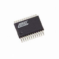
IC MCU FLASH 4K TX 433MHZ 24SSOP
Manufacturer
Atmel
Datasheet
1.ATAM862P-TNQY4D.pdf
(110 pages)
Specifications of ATAM862P-TNSY4D
Applications
UHF ASK/FSK
Core Processor
MARC4
Program Memory Type
FLASH (4 kB)
Controller Series
MARC4 4-Bit
Ram Size
256 x 4
Interface
SSI
Number Of I /o
11
Voltage - Supply
1.8 V ~ 4 V
Operating Temperature
-40°C ~ 125°C
Mounting Type
Surface Mount
Package / Case
24-SSOP
Processor Series
ATAM862x
Core
MARC4
Data Bus Width
4 bit
Mounting Style
SMD/SMT
Lead Free Status / RoHS Status
Lead free / RoHS Compliant
16.7
16.7.1
16.7.2
20
Interrupt Structure
ATAM862-4
Interrupt Processing
Interrupt Latency
The microcontroller can handle interrupts with eight different priority levels. They can be gener-
ated from the internal and external interrupt sources or by a software interrupt from the CPU
itself. Each interrupt level has a hard-wired priority and an associated vector for the service rou-
tine in the EEPROM (see
processing of interrupts by resetting the interrupt enable flag (I) in the CCR. An interrupt occur-
rence will still be registered, but the interrupt routine only started after the I-flag is set. All
interrupts can be masked, and the priority individually software configured by programming the
appropriate control register of the interrupting module (see section
page
For processing the eight interrupt levels, the microcontroller includes an interrupt controller with
two 8-bit wide interrupt pending and interrupt active registers. The interrupt controller samples all
interrupt requests during every non-I/O instruction cycle and latches these in the interrupt pend-
ing register. If no higher priority interrupt is present in the interrupt active register, it signals the
CPU to interrupt the current program execution. If the interrupt enable bit is set, the processor
enters an interrupt acknowledge cycle. During this cycle a short call (SCALL) instruction to the
service routine is executed and the current PC is saved on the return stack. An interrupt service
routine is completed with the RTI instruction. This instruction resets the corresponding bits in the
interrupt pending/active register and fetches the return address from the return stack to the pro-
gram counter. When the interrupt enable flag is reset (triggering of interrupt routines is disabled),
the execution of new interrupt service routines is inhibited but not the logging of the interrupt
requests in the interrupt pending register. The execution of the interrupt is delayed until the inter-
rupt enable flag is set again. Note that interrupts are only lost if an interrupt request occurs while
the corresponding bit in the pending register is still set (i.e., the interrupt service routine is not yet
finished).
It should be noted that automatic stacking of the RBR is not carried out by the hardware and so
if ROM banking is used, the RBR must be stacked on the expression stack by the application
program and restored before the RTI. After a master reset (power-on, brown-out or watchdog
reset), the interrupt enable flag and the interrupt pending and interrupt active register are all
reset.
The interrupt latency is the time from the occurrence of the interrupt to the interrupt service rou-
tine being activated. This is extremely short (taking between 3 to 5 machine cycles depending
on the state of the core).
32).
Table 16-1 on page
21). The programmer can postpone the
“Peripheral Modules” on
4551G–4BMCU–07/07


