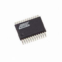
ATAM862P-TNSY4D Atmel, ATAM862P-TNSY4D Datasheet - Page 59

ATAM862P-TNSY4D
Manufacturer Part Number
ATAM862P-TNSY4D
Description
IC MCU FLASH 4K TX 433MHZ 24SSOP
Manufacturer
Atmel
Datasheet
1.ATAM862P-TNQY4D.pdf
(110 pages)
Specifications of ATAM862P-TNSY4D
Applications
UHF ASK/FSK
Core Processor
MARC4
Program Memory Type
FLASH (4 kB)
Controller Series
MARC4 4-Bit
Ram Size
256 x 4
Interface
SSI
Number Of I /o
11
Voltage - Supply
1.8 V ~ 4 V
Operating Temperature
-40°C ~ 125°C
Mounting Type
Surface Mount
Package / Case
24-SSOP
Processor Series
ATAM862x
Core
MARC4
Data Bus Width
4 bit
Mounting Style
SMD/SMT
Lead Free Status / RoHS Status
Lead free / RoHS Compliant
23.2
4551G–4BMCU–07/07
Timer/Counter Modes
A special feature of this timer is the trigger- and single-action mode. In trigger mode, the counter
starts counting triggered by the external signal at its input. In single-action mode, the counter
counts only one time up to the programmed compare match event. These modes are very useful
for modulation, demodulation, signal generation, signal measurement and phase controlling. For
phase controlling, the timer input is protected against negative voltages and has zero-cross
detection capability.
Timer 3 has a modulator output stage and input functions for demodulation. As modulator it
works together with Timer 2 or the serial interface. When the shift register is used for modulation
the data shifted out of the register is encoded bitwise. In all demodulation modes, the decoded
data bits are shifted automatically into the shift register.
Timer 3 has 6 timer modes and 6 modulator/demodulator modes. The mode is set via the Timer
3 Mode Register T3M.
In all these modes, the compare register and the compare-mode register belonging to it define
the counter value for a compare match and the action of a compare match. A match of the cur-
rent counter value with the content of one compare register triggers a counter reset, a Timer 3
interrupt or the toggling of the output flip-flop. The compare mode registers T3M1 and T3M2
contain the mask bits for enabling or disabling these actions.
The counter can also be enabled to execute single actions with one or both compare registers. If
this mode is set the corresponding compare match event is generated only once after the
counter start.
Most of the timer modes use their compare registers alternately. After the start has been acti-
vated, the first comparison is carried out via the compare register 1, the second is carried out via
the compare register 2, the third is carried out again via the compare register 1 and so on. This
makes it easy to generate signals with constant periods and variable duty cycle or to generate
signals with variable pulse and space widths.
If single-action mode is set for one compare register, the comparison is always carried out after
the first cycle via the other compare register.
The counter can be started and stopped via the control register T3C. This register also controls
the initial level of the output before start. T3C contains the interrupt mask for a T3I input
interrupt.
Via the Timer 3 clock-select register, the internal or external clock source can be selected. This
register selects also the active edge of the external input. An edge at the external input T3I can
generate also an interrupt if the T3EIM bit is set and the Timer 3 is stopped (T3R = 0) in the T3C
register.
ATAM862-4
59


