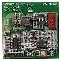
MCP1631RD-MCC1 Microchip Technology, MCP1631RD-MCC1 Datasheet - Page 121

MCP1631RD-MCC1
Manufacturer Part Number
MCP1631RD-MCC1
Description
REFERENCE DESIGN FOR MCP1631HV
Manufacturer
Microchip Technology
Type
Battery Managementr
Datasheets
1.MCP1631VHVT-330EST.pdf
(34 pages)
2.MCP1631HV-330EST.pdf
(54 pages)
3.MCP1631RD-MCC2.pdf
(20 pages)
4.MCP1631RD-MCC2.pdf
(328 pages)
5.MCP1631RD-MCC1.pdf
(28 pages)
Specifications of MCP1631RD-MCC1
Main Purpose
Power Management, Battery Charger
Embedded
Yes, MCU, 8-Bit
Utilized Ic / Part
MCP1631HV, PIC16F883
Primary Attributes
1 ~ 2 Cell- Li-Ion, 1 ~ 4 Cell- NiCd/NiMH
Secondary Attributes
Status LEDs
Supported Devices
MCP1631HV, PIC16F883 Device Type
Tool / Board Applications
Power Management-Battery Management
Development Tool Type
Reference Design
Input Voltage
5.5 V to 16 V
Product
Power Management Modules
Mcu Supported Families
MCP1631HV/PIC16F883 Family
Silicon Manufacturer
Microchip
Silicon Core Number
MCP1631HV
Kit Application Type
Reference Design
Application Sub Type
Battery Charger
Kit Contents
Board Only
Lead Free Status / RoHS Status
Lead free / RoHS Compliant
For Use With/related Products
MCP1631HV, PIC16F883
Lead Free Status / RoHS Status
Lead free / RoHS Compliant
- MCP1631VHVT-330EST PDF datasheet
- MCP1631HV-330EST PDF datasheet #2
- MCP1631RD-MCC2 PDF datasheet #3
- MCP1631RD-MCC2 PDF datasheet #4
- MCP1631RD-MCC1 PDF datasheet #5
- Current page: 121 of 328
- Download datasheet (6Mb)
An example of the complete eight-word write sequence
is shown in Example 10-4. The initial address is loaded
into the EEADRH and EEADR register pair; the eight
words of data are loaded using indirect addressing.
EXAMPLE 10-4:
© 2009 Microchip Technology Inc.
LOOP
;;;;;;;;;;;;;;;;;;;;;;;;;;;;;;;;;;;;;;;;;;;;;;;;;;;;;;;;;;;;;;;;;;;;;;;;;;;;;;;;;;
; This write routine assumes the following:
;
;
;
;
BANKSEL
MOVF
MOVWF
MOVF
MOVWF
MOVF
MOVWF
MOVF
MOVWF
INCF
MOVF
MOVWF
INCF
BANKSEL
BSF
BSF
BCF
BTFSC
GOTO
;;;;;;;;;;;;;;;;;;;;;;;;;;;;;;;;;;;;;;;;;;;;;;;;;;;;;;;;;;;;;;;;;;;;;;;;;;;;;;;;;;
;
MOVLW
MOVWF
MOVLW
MOVWF
BSF
NOP
NOP
;;;;;;;;;;;;;;;;;;;;;;;;;;;;;;;;;;;;;;;;;;;;;;;;;;;;;;;;;;;;;;;;;;;;;;;;;;;;;;;;;;
BCF
BSF
BANKSEL
MOVF
INCF
ANDLW
SUBLW
BTFSS
GOTO
A valid starting address (the least significant bits = '000')
is loaded in ADDRH:ADDRL
ADDRH, ADDRL and DATADDR are all located in data memory
EEADRH
ADDRH,W
EEADRH
ADDRL,W
EEADR
DATAADDR,W
FSR
INDF,W
EEDATA
FSR,F
INDF,W
EEDATH
FSR,F
EECON1
EECON1,EEPGD ; Point to program memory
EECON1,WREN ; Enable writes
INTCON,GIE
INTCON,GIE
$-2
55h
EECON2
0AAh
EECON2
EECON1,WR
EECON1,WREN ; Disable writes
INTCON,GIE
EEADR
EEADR, W
EEADR,F
0x0F
0x0F
STATUS,Z
LOOP
WRITING TO FLASH PROGRAM MEMORY
; Load initial address
;
;
;
; Load initial data address
;
; Load first data byte into lower
;
; Next byte
; Load second data byte into upper
;
;
; Disable interrupts (if using)
; See AN576
; Start of required write sequence:
; Write 55h
;
; Write 0AAh
; Set WR bit to begin write
; Required to transfer data to the buffer
; registers
; Enable interrupts (comment out if not using interrupts)
; Increment address
; Indicates when sixteen words have been programmed
;
;
;
;
; Exit on a match,
; Continue if more data needs to be written
Required Sequence
0x0F = 16 words
0x0B = 12 words (PIC16F884/883/882 only)
0x07 = 8 words
0x03 = 4 words(PIC16F884/883/882 only)
PIC16F882/883/884/886/887
DS41291F-page 119
Related parts for MCP1631RD-MCC1
Image
Part Number
Description
Manufacturer
Datasheet
Request
R

Part Number:
Description:
REFERENCE DESIGN MCP1631HV
Manufacturer:
Microchip Technology
Datasheet:

Part Number:
Description:
REF DES BATT CHARG OR LED DRIVER
Manufacturer:
Microchip Technology
Datasheet:

Part Number:
Description:
Manufacturer:
Microchip Technology Inc.
Datasheet:

Part Number:
Description:
Manufacturer:
Microchip Technology Inc.
Datasheet:

Part Number:
Description:
Manufacturer:
Microchip Technology Inc.
Datasheet:

Part Number:
Description:
Manufacturer:
Microchip Technology Inc.
Datasheet:

Part Number:
Description:
Manufacturer:
Microchip Technology Inc.
Datasheet:

Part Number:
Description:
Manufacturer:
Microchip Technology Inc.
Datasheet:

Part Number:
Description:
Manufacturer:
Microchip Technology Inc.
Datasheet:

Part Number:
Description:
Manufacturer:
Microchip Technology Inc.
Datasheet:


